A vacuum pump structure
A vacuum pump and vacuum chamber technology, applied in the direction of pumps, machines/engines, mechanical equipment, etc., can solve problems such as inability to spread lubricating oil, achieve good sealing, reduce the probability of damage, and avoid excessive temperature rise.
- Summary
- Abstract
- Description
- Claims
- Application Information
AI Technical Summary
Problems solved by technology
Method used
Image
Examples
Embodiment Construction
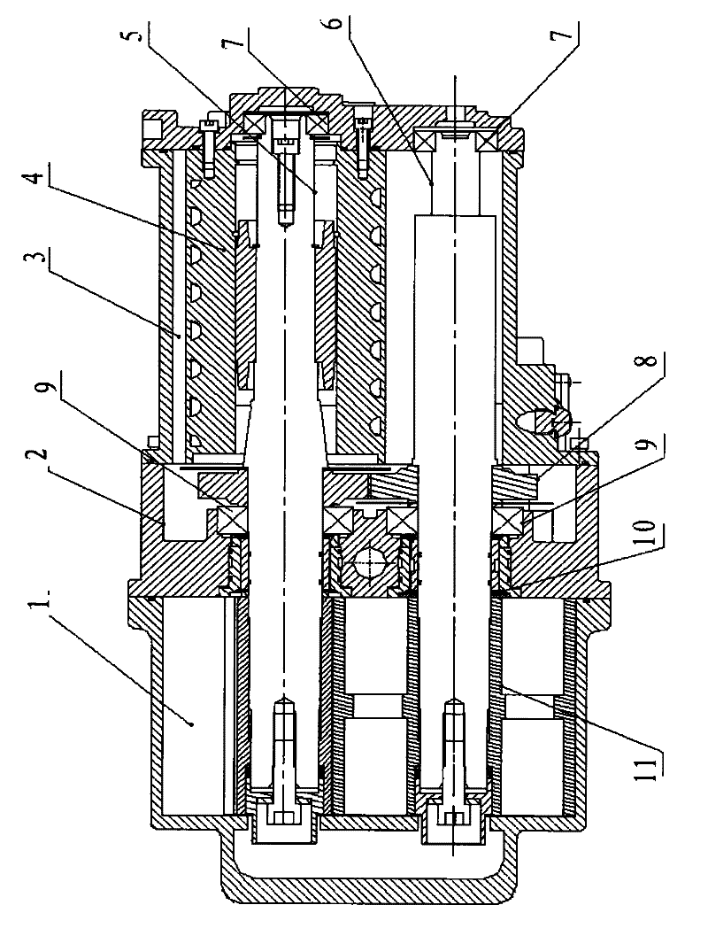
[0018] The present invention is a vacuum pump structure, its structure diagram is as follows: figure 1 shown. The vacuum pump cavity is composed of a vacuum cavity 1, a gear box 2 and a motor cavity 3. The shielded motor 4 is fixed in the motor cavity 3, the motor main shaft 5 passes through the center of the shielded motor 4, and is supported by the support bearing A7 arranged in the motor cavity and the support bearing B9 arranged in the gearbox, and the driven shaft 6 is also supported by the support bearing A7 and supporting bearing B9 are supported, and the outstretched ends of the motor main shaft 5 and the driven shaft 6 are in the vacuum cavity 1 . The Roots rotor 11 is fixed on the extended ends of the motor main shaft 5 and the driven shaft 6 by means of expansion sleeve assemblies. The shaft seal assembly is installed in the center of the gear box 2 and sleeved on the motor main shaft 5 and the driven shaft 6 to block the vacuum chamber 1 and the motor chamber 3 ....
PUM
 Abstract
Description
Claims
Application Information
 - R&D
- Intellectual Property
- Life Sciences
- Materials
- Tech Scout
- Unparalleled Data Quality
- Higher Quality Content
- 60% Fewer Hallucinations
Browse by: Latest US Patents, China's latest patents, Technical Efficacy Thesaurus, Application Domain, Technology Topic, Popular Technical Reports.
© 2025 PatSnap. All rights reserved.Legal|Privacy policy|Modern Slavery Act Transparency Statement|Sitemap|About US| Contact US: help@patsnap.com


