
Hydraulic rotary casing guide shoe

A technology of casing guiding shoes and rotating sleeves, which is applied in the direction of casing, drill pipe, drilling equipment, etc., can solve the problems of prolonging the cementing operation period, hindering the lowering of casing guiding shoes, and the lowering resistance of casing guiding shoes, and achieving Ease of popularization, simple structure, and the effect of reducing resistance

Inactive Publication Date: 2011-12-14
SICHUAN RONGRUI HUABAO TECH
View PDF9 Cites 16 Cited by
  • Summary
  • Abstract
  • Description
  • Claims
  • Application Information

AI Technical Summary

Problems solved by technology

[0002] In the process of oil drilling operations, considering that the casing has a certain rigidity and the outer diameter is larger than the outer diameter of the drilling tool, it is easy to encounter obstructions and complex situations during the cementing operation of the casing, prolonging the cementing operation cycle and high operating risks
Generally, a casing guide shoe is installed on the top of the casing to assist in the process. The casing guide shoe is a conical or cannonball-shaped short joint connected to the bottom of the casing. Scraping of wellbore mud, sand and rocks at the bottom of the casing will cause casing blockage and lowering to be blocked. However, the casing guide shoes of the existing structure are generally arc-shaped head structures made of drillable materials in order to realize the guiding function. , to reduce the resistance generated when the casing guide shoe is lowered, but if the sediment accumulation in the wellbore causes the wellbore gap to be smaller than the cross-sectional area of ​​the casing guide shoe, this will still cause resistance to the lowering of the casing guide shoe, and In the process of actual operation, there are generally silt in the wellbore that hinders the lowering of the casing guide shoe. Therefore, in order to overcome this drawback, it is necessary to make further improvements to the structure of the existing casing guide shoe.

Method used


Image

  • Hydraulic rotary casing guide shoe
  • Hydraulic rotary casing guide shoe
  • Hydraulic rotary casing guide shoe

Examples


Embodiment 1

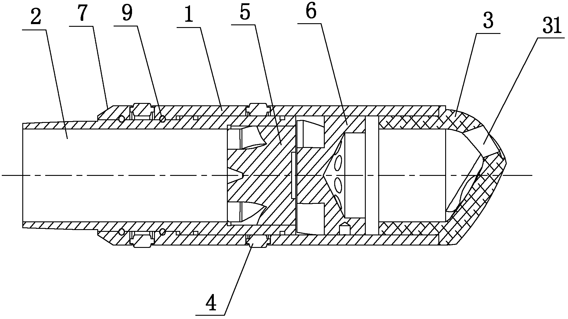
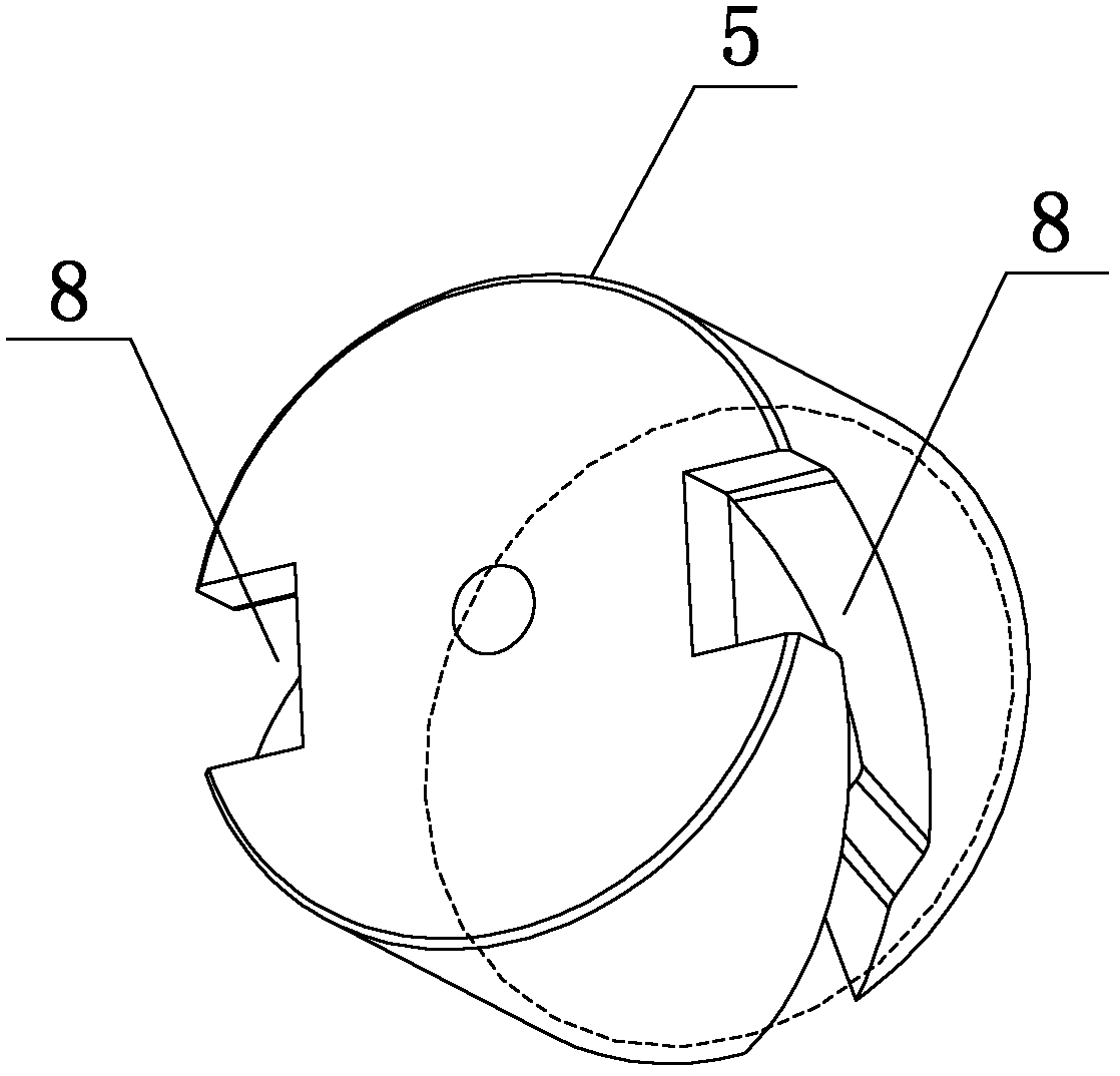
[0022] Such as figure 1 As shown, a hydraulic rotary casing guide shoe provided by the present invention includes a hollow suspension shell 1, a casing joint 2 is installed at the rear end of the suspension shell 1, and a hollow eccentric toe guide 3 is installed at the front end. , at the same time, in order to form a perfect matching relationship between the hydraulic rotating casing guide shoe and the casing, it is preferable to set the suspension outer casing 1 and the casing joint 2 in a circular tubular shape; the front end of the eccentric guide shoe head 3 is provided with an axial Eccentric hole 31, its end stretches in the cavity of suspension shell 1 inside, and the end of eccentric guide toe cap 3 is also provided with a plurality of through holes, and a plurality of through holes on the end of eccentric guide toe cap 3 are all connected with the inside The cavities are connected, and the rotating sleeve guide shoe also includes a rotating shaft 5 and a rotating sl...

Embodiment 2

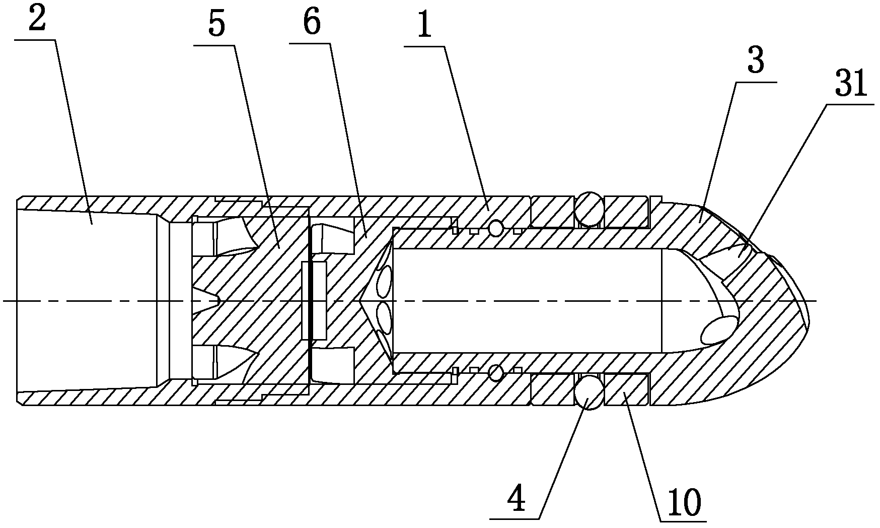
[0028] Such as figure 2 As shown, a hydraulic rotary casing guide shoe provided by the present invention includes a hollow suspension shell 1, a casing joint 2 is installed at the rear end of the suspension shell 1, and a hollow eccentric toe guide 3 is installed at the front end. , at the same time, in order to make the hydraulic rotary casing shoe and the casing form a perfect matching relationship, the suspension shell 1 and the casing joint 2 are both in the shape of a circular tube; the front end of the eccentric shoe head 3 is provided with an axial eccentric Hole 31, its end stretches in the cavity of hanging shell 1 inside, and the end of eccentric guide toe cap 3 is also provided with a plurality of through holes, and the plurality of through holes on the end of eccentric guide toe cap 3 are all connected with the inside. The cavities are connected, and the said rotating sleeve guide shoe also includes a rotating shaft 5 and a rotating sleeve 6, both of which are ins...


PUM


Abstract

The invention discloses a hydraulically-operated rotary casing guide shoe, and belongs to an assorted tool for a casing pipe in petroleum drilling operation. The hydraulically-operated rotary casing guide shoe comprises a hollow hanging shell (1), a rotary shaft (5) and a rotary sleeve (6), wherein a casing pipe joint (2) is arranged at the rear end of the hanging shell (1), and a hollow eccentric guide shoe head (3) is arranged at the front end of the hanging shell (1); an axial eccentric hole (31) is formed at the front end of the eccentric guide shoe head (3), and the tail end of the eccentric guide shoe head (3) extends into a cavity inside the hanging shell (1); a plurality of through holes at the tail end of the eccentric guide shoe head (3) are communicated with a cavity inside theeccentric guide shoe head; the rotary shaft (5) and the rotary sleeve (6) are arranged inside the hanging shell (1); one end of the rotary sleeve (6) is fixed to the tail end of the eccentric guide shoe head (3); and a gap is reserved between the other end of the rotary sleeve (6) and the rotary shaft (5). The externally-hung hydraulically-operated rotary casing guide shoe has a simple structure,can be used in various petroleum drilling occasions, is suitable for industrial production and is easy to popularize.

Description

technical field [0001] The invention relates to a supporting tool for oil drilling operation casing, more specifically a hydraulic rotary casing guide shoe. Background technique [0002] In the process of oil drilling operations, considering that the casing has a certain rigidity and the outer diameter is larger than the outer diameter of the drilling tool, it is easy to encounter obstructions and complex situations during the cementing operation of the casing, prolonging the cementing operation cycle and high operating risks . Generally, a casing guide shoe is installed on the top of the casing to assist in the process. The casing guide shoe is a conical or cannonball-shaped short joint connected to the bottom of the casing. Scraping of wellbore mud, sand and rocks at the bottom of the casing will cause casing blockage and lowering to be blocked. However, the casing guide shoes of the existing structure are generally arc-shaped head structures made of drillable materials i...

Claims


Application Information

Patent Timeline
Patent Type & Authority Applications(China)
IPC IPC(8): E21B17/14
Inventor 吴华彭文玥王建东
Owner SICHUAN RONGRUI HUABAO TECH
Learn More