
An intelligent electronic lock

An electronic lock and intelligent technology, applied in the field of locks, can solve problems such as liquid leakage, damage, battery damage, etc., and achieve the effect of a large number of passwords, ensuring security, and high security

Active Publication Date: 2011-12-14
BRINGSPRING SCIENCE & TECHNOLOGY CO LTD
View PDF6 Cites 3 Cited by
  • Summary
  • Abstract
  • Description
  • Claims
  • Application Information

AI Technical Summary

Problems solved by technology

[0004] Aiming at the disadvantages of electronic locks in the prior art that are easy to cause damage to the battery, leakage, damage, etc., the technical problem to be solved by the present invention is to provide an electronic lock with a memory function, no power in the lock, and a long service life.

Method used


Image

  • An intelligent electronic lock
  • An intelligent electronic lock
  • An intelligent electronic lock

Examples


Embodiment Construction

[0031] The intelligent electronic lock of the present invention is widely used in important facilities such as communication optical cable transfer boxes, base station equipment boxes, electric energy meter boxes, and metering cabinets. It includes three parts: the lock body, the key, and the setter. On-site work plan for inspection and replacement of equipment and metering devices, setting the operating authority and operating time of the intelligent electronic lock.

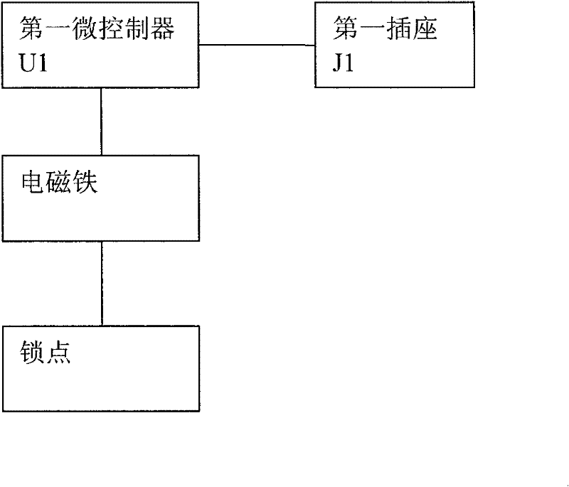
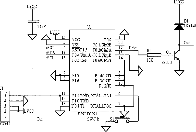
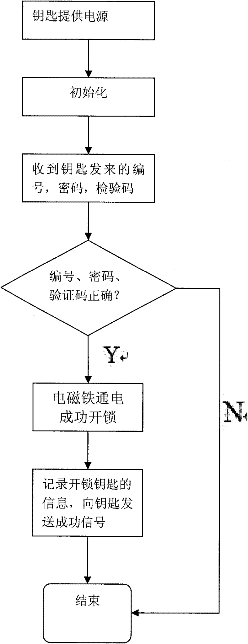
[0032] Such as figure 1 , 2 , Shown in 4, 5, lock body has the first micro-controller U1, coil and lock point, the output terminal of the first micro-controller is connected with electromagnet, and lock point is located in the magnetic force range of electromagnet; The first micro-controller The device U1 is connected with the first socket J1; the key has a second micro-controller U4, a storage module U3, a clock module U5 and a battery, the second micro-controller U4 is the control core of the key, connected ...


PUM


Abstract

The invention relates to a smart electronic lock comprising a lock body, a key and a setter, wherein the lock body is provided with a first microcontroller, a coil and a lock point; the output end of the first microcontroller is connected to an electromagnet; the lock point is arranged within the magnetic action range of the electromagnet; the first microcontroller is connected to a first socket;the key is provided with a second microcontroller, a memory module, a clock module and a battery; the second microcontroller is connected to a plug and in communication with the first microcontroller; the battery serves as a working power source for the key and the lock body; the second microcontroller is connected to the memory module and the clock module; the setter is provided with a microcontroller and a second socket; the microcontroller is connected to the key plug via the second socket; and a communication module is integrated inside each of the first microcontroller, the second microcontroller and the setter. The smart electronic lock has a large number of passwords and is high in safety, and also guarantees the stable operation of the electronic lock and devices inside a box; andthe management of the service field operations of the field equipment and devices within a communication company or a power enterprise is perfected.

Description

technical field [0001] The invention relates to a lock, in particular to an intelligent electronic lock. Background technique [0002] Communication optical cable transfer boxes of communication companies, base station equipment boxes, electric energy meter boxes of power companies, and metering cabinets mostly use mechanical locks as protection devices. The mechanical locks still use the traditional method. After inserting the lock cylinder, press back the copper column in the lock cylinder, so that the lock cylinder can be rotated to unlock. The password of the mechanical lock can be clearly displayed on the key, which has low security. By duplicating the key, the communication optical cable transfer box, base station equipment box, electric energy meter box, and metering cabinet can be opened. The safe and accurate operation of the system not only causes the economic loss of the enterprise, but also makes it impossible for the enterprise to comprehensively manage the on-...

Claims


Application Information

Patent Timeline
Patent Type & Authority Applications(China)
IPC IPC(8): E05B49/00E05B47/06E05B19/00E05B65/52
Inventor 付永全马林梁倩孙家奇魏国生
Owner BRINGSPRING SCIENCE & TECHNOLOGY CO LTD
Learn More