Method for machining oil seal shaft

A processing method and oil seal technology, which are applied in metal processing equipment, manufacturing tools, machine tools designed for grinding the rotating surface of workpieces, etc., can solve the problem of not being able to meet the oil seal without oil leakage, and achieve the effect of a simple method

Active Publication Date: 2013-04-10
DALIAN DEMAISHI PRECISION TECH CO LTD
View PDF4 Cites 1 Cited by
  • Summary
  • Abstract
  • Description
  • Claims
  • Application Information

AI Technical Summary

Problems solved by technology

To sum up, none of the four current processing methods can meet the requirement of no oil leakage during the oil seal.

Method used


Image

  • Method for machining oil seal shaft
  • Method for machining oil seal shaft
  • Method for machining oil seal shaft

Examples


Embodiment 1

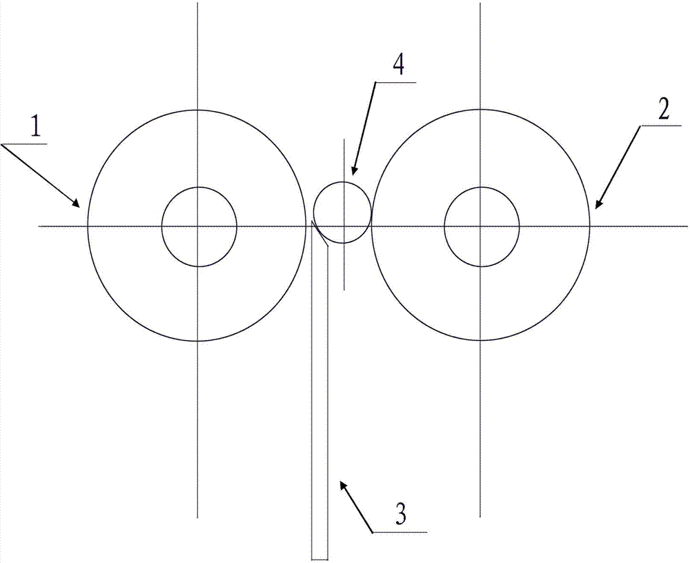
[0027] To refit the existing centerless grinder, first choose CBN grinding wheel (CBN140 / 170B100) as the centerless grinder grinding wheel 1, which meets the following requirements: roughness: Ra0.2~0.4 and Rz<4, and the grain direction produced after grinding should be parallel And perpendicular to the center line of the shaft, the grinding wheel is not easy to wear, and the thickness is equal to the axial length of the oil seal groove of the shaft. One side of the grinding wheel is provided with a guide wheel 2, the axes of the two are parallel, the axis of the guide wheel and the axis of the grinding wheel are on the same horizontal plane, and the distance between the grinding wheel and the guide wheel = diameter of the workpiece - depth of the oil seal groove. The axle of this guide wheel links to each other with the motor output shaft. A vertical supporting plate 3 is arranged between the emery wheel and the guide, and the supporting plate top surface is an inclined p...


PUM


Abstract

The invention discloses a method for machining an oil seal shaft. In the method, the conventional centerless grinding machine is retrofitted; a grinding wheel of the centerless grinding machine is required to meet the following requirements that: the roughtness Ra is 0.2 to 0.4 and Rz is less than 4; texture directions produced by grinding are required to be parallel with one another and verticalto the central line of the shaft; the grinding wheel is required to be abrasion-proof; the thickness of the grinding wheel is equal to the axial length of an oil seal slot of the shaft; a guide wheelis arranged on one side of the grinding wheel; the axial lines of the grinding wheel and the guide wheel are parallel with each other; a distance between the grinding wheel and the guide wheel is equal to a difference between the diameter of a workpiece and the depth of the oil seal slot; the axle of the guide wheel is connected with the output shaft of a motor; a vertical supporting plate is arranged between the grinding wheel and the guide wheel; the workpiece with a horizontal axial line is arranged on the top face of the supporting plate; and a rotating roller parallel to the axial line of the workpiece is arranged above the position of the workpiece. A machining method for statically grinding comprises the following steps of: positioning the workpiece through the grinding wheel, the guide wheel, the supporting plate and the rotating roller; and starting the motor and injecting grinding solution into a part to be ground for grinding. The roughness and the texture directions of theoil seal slot machined by using the method can completely meet the technical requirements of the oil seal shaft.

Description

technical field [0001] The invention relates to a processing method of a metal shaft, in particular to a processing method of an oil-sealed shaft. Background technique [0002] The oil seal shaft is a high-precision shaft used in automobiles and matched with oil seals. The oil seal shaft is provided with an oil seal groove, and its technical requirements are as follows: ①Roughness: Ra0.2~0.4 and Rz<4. ②The grain direction produced after grinding should be parallel and perpendicular to the shaft centerline. If the roughness and grain direction of the oil seal groove of the oil seal shaft do not meet the requirements, oil leakage will occur. At present, there are mainly the following traditional processing methods for oil tanks: 1. Finishing with lathe: Through experiments, we found that the roughness curve of turning is connected by clear triangles, and the processing property is that the valley (groove) of roughness is a line. A helix that continues from one end of the...

Claims


Application Information

Patent Timeline
Patent Type & Authority Patents(China)
IPC IPC(8): B24B5/18
Inventor 刘国龙林光贤
Owner DALIAN DEMAISHI PRECISION TECH CO LTD
Why Eureka
Try Eureka