Wind farm wireless meteorological data monitoring device

A technology of meteorological data and monitoring devices, which is applied in the field of meteorological data monitoring devices, can solve the problems of low instrument reliability, high price, application limitations, etc., and achieve the goal of saving evaluation costs and manpower input, low cost, and strong adaptability to the environment Effect

Inactive Publication Date: 2011-12-07
HARBIN UNIV OF SCI & TECH
View PDF3 Cites 13 Cited by
  • Summary
  • Abstract
  • Description
  • Claims
  • Application Information

AI Technical Summary

Problems solved by technology

1. The mechanical type is mainly the wind cup type and the wind wheel type. Since the runner is a movable component, factors such as mechanical friction, sediment and dust accumulation make the reliability of the instrument not high and the error is large; 2. The dynamic pressure type is based on the complete Hosting is the main method, and the error is relatively large when measuring small wind speeds; 3. Ultrasonic anemometers have high precision, but they are expensive; 4. Thermal anemometers mainly include hot-wire types, which are widely used in the field of gas detection, but are expensive
Therefore, the application is limited by the problem of

Method used


Image

  • Wind farm wireless meteorological data monitoring device
  • Wind farm wireless meteorological data monitoring device
  • Wind farm wireless meteorological data monitoring device

Examples


specific Embodiment approach 1

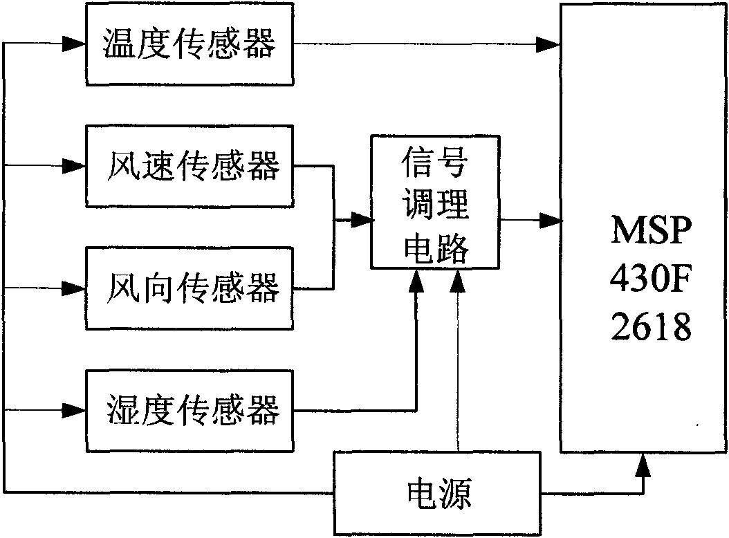
[0010] Specific implementation mode one: combine figure 1 , figure 2 , image 3 , Figure 4 , Figure 5 The present embodiment will be described. This embodiment is made up of data acquisition module, ZigBee wireless transmission module and data processing module, and data acquisition module is connected with one end of ZigBee wireless transmission module, and the other end of ZigBee wireless transmission module is connected with data processing module, carries out data transmission; Described The data acquisition module is composed of data acquisition MCU (data acquisition MCU model is MSP430F2618), wind direction sensor, wind speed sensor, temperature sensor, humidity sensor and power supply, wind direction sensor, wind speed sensor (wind direction sensor, wind speed sensor adopts hot film wind sensor) and The output terminal of the humidity sensor (the humidity sensor adopts HS 1101 polymer capacitive humidity sensor) is connected to the input terminal of the condition...

specific Embodiment approach 2

[0011] Specific implementation mode two: combination figure 1 , Figure 5 The present embodiment will be described. There are 5 buttons in this embodiment, which are respectively , , , and keys, and the corresponding functions are to enter the setting state and select and set the collection time. bit, add one operation, subtract one operation and system reset to the selected bit.

specific Embodiment approach 3

[0012] Specific implementation mode three: combination figure 1 , Figure 4 The present embodiment will be described. The real-time clock in this embodiment is used to calibrate the time of the meteorological data received each time, and obtain the time when the data is processed. MCU with real-time clock using I 2 C communication method.


PUM


Abstract

A wireless meteorological data monitoring device for a wind farm relates to a meteorological data monitoring device, which solves the problems of low reliability, large error and high price of the monitoring device. The data collected and output by the data acquisition module of the present invention is transmitted to the data processing module through the ZigBee wireless transmission module. The advantages of the present invention are that the ultra-low power consumption MCU is used to make the power consumption of the device very low; the use of a hot film wind sensor makes the device high in precision, low in cost, good in durability, strong in adapting to the environment, and wide in application temperature range; adopting Zigbee wireless The transmission module solves the problem of wired transmission of the device, reduces the size and quality of the device, and saves the cost of wind resource assessment and manpower input in the early stage.

Description

technical field [0001] The invention relates to a meteorological data monitoring device. In particular, the invention relates to a wireless meteorological data monitoring device for a wind farm. Background technique [0002] At present, the existing wind farm meteorological monitoring devices are divided into four types according to different working principles: mechanical type, dynamic pressure type, ultrasonic type and thermal type. 1. The mechanical type is mainly the wind cup type and the wind wheel type. Since the runner is a movable component, factors such as mechanical friction, sediment and dust accumulation make the reliability of the instrument not high and the error is large; 2. The dynamic pressure type is based on the complete Hosting is the main method, and the error is relatively large when measuring small wind speeds; 3. Ultrasonic anemometers have high precision, but they are expensive; 4. Thermal anemometers mainly include hot-wire types, which are widely ...

Claims


Application Information

Patent Timeline
IPC IPC(8): G08C17/02G01W1/02
CPCY02A90/10
Inventor 于春雨丁喜波孙永全刘新华
Owner HARBIN UNIV OF SCI & TECH
Why Eureka
Try Eureka