
Touch control type liquid crystal display

A liquid crystal display and touch technology, applied in static indicators, instruments, optics, etc., can solve the problems of weak support, poor induction, and increased assembly time, so as to improve the metal interference problem, take into account the convenience of assembly, and simplify Effect of material type

Inactive Publication Date: 2013-05-22
AU OPTRONICS CORP
View PDF8 Cites 0 Cited by
  • Summary
  • Abstract
  • Description
  • Claims
  • Application Information

AI Technical Summary

Problems solved by technology

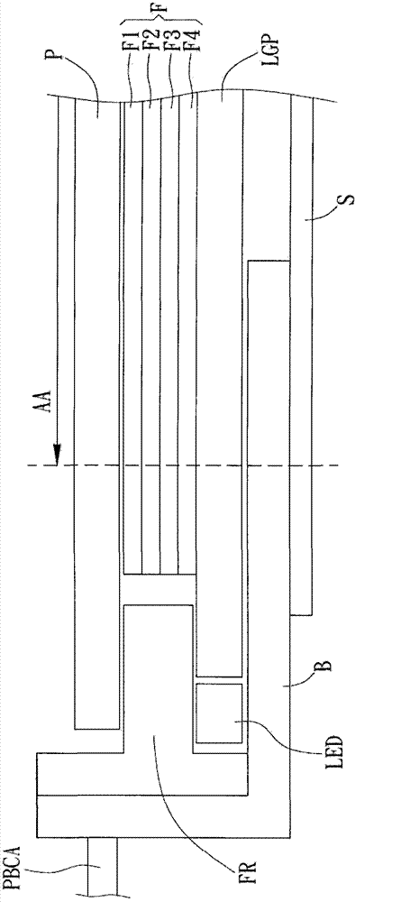
like figure 1 As shown, since the sensing plate S is attached to the back of the display panel P, if there is a metal substance between the sensing plate S and the active area (active area) AA of the display panel P, the sensing of the sensing plate S will increase. Causes interference, so the disadvantage of this structure is: the area of ​​the back iron frame B is too large and extends between the sensing board S and the visible area AA of the display panel P, causing the sensing board S to be interfered by metal substances and cause poor induction
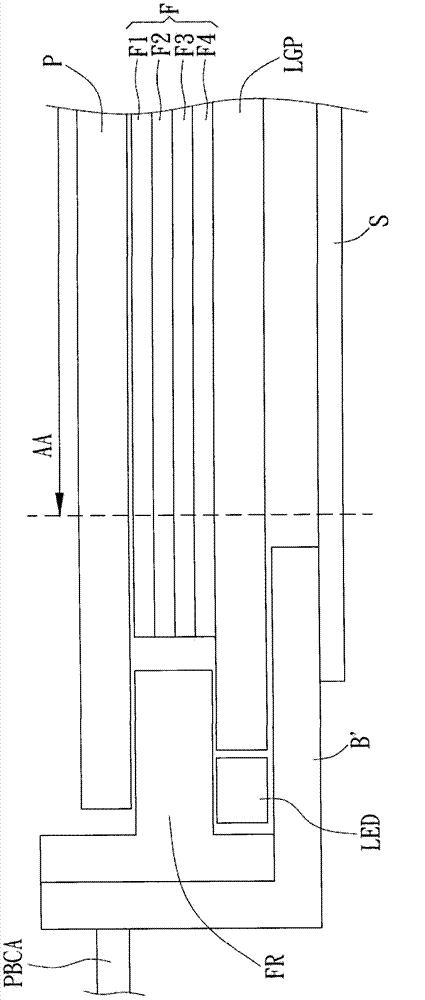
However, in order to arrange the sensing board S under the visible area AA of the display panel P, the area of ​​the iron frame of the LED holder H must be reduced, resulting in weakened support strength.
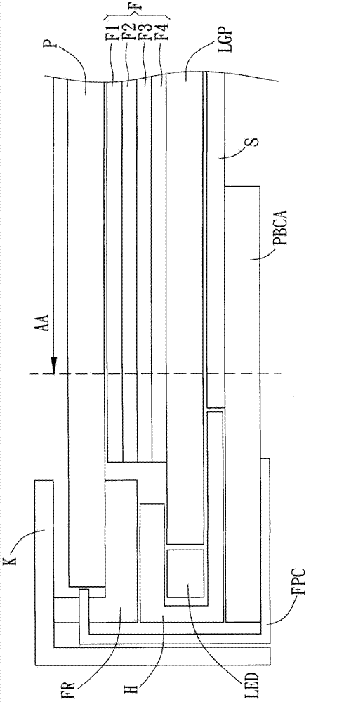
In addition, if Figure 3B As shown, in the actual assembly process, it is also necessary to pull the PBCA board downwards first, and then insert the induction board S, which not only increases the assembly man-hours, but also may cause flexible circuit boards (Flexible PCBs) due to the PBCA boards being pulled downwards. Printed Circuit, FPC) is damaged by bending

Method used


Image

  • Touch control type liquid crystal display
  • Touch control type liquid crystal display
  • Touch control type liquid crystal display

Examples


Embodiment Construction

[0044] A preferred embodiment of the present invention is a touch-sensitive liquid crystal display. In this embodiment, the touch-sensitive liquid crystal display at least includes a display panel, a backlight module, a sensor panel and a touch panel. Wherein, the backlight module is an edge-light LED backlight module, but not limited thereto.

[0045] Please refer to Figure 4 , Figure 4 A schematic cross-sectional view of the touch-sensitive liquid crystal display T along the X-X line and the Y-Y line in this embodiment is shown. Such as Figure 4 As shown, the touch-sensitive liquid crystal display T includes a backlight module 4 , a plastic frame CT, a sensor board 43 , a display panel 5 , a touch panel 6 and a protective glass 7 . The display panel 5 is arranged above the backlight module 4; the sensor board 43 is arranged below the backlight module 4; the touch panel 6 is arranged above the display panel 5; the protective glass 7 is arranged above the touch panel 6;...


PUM


Abstract

A touch Display apparatus is disclosed. The touch Display apparatus includes a backlight module and a sensing plate. The backlight module includes a support member, a light guide plate, and a backlight source. The support member is formed by a non-metallic material and has a bottom and a plurality of sidewalls. The sides of the bottom connect with the sidewalls respectively to form a containing space. The light guide plate is disposed in the containing space and has a light emitting surface. A side of the containing space has a light incident end. The backlight source is disposed corresponding to the light incident end in the containing space. The backlight source generates a light emitting to the light incident end. The sensing plate is disposed on a lower surface of the bottom and senses an action of an item above the support member through an electromagnetic reaction.

Description

technical field [0001] The invention relates to a liquid crystal display, in particular to a touch-sensitive liquid crystal display using metal-free micro-foamed polyethylene terephthalate (MCPET) as the supporting structure of its backlight module. Background technique [0002] In recent years, with the continuous development of science and technology, various thin, light and small portable electronic products have appeared on the market, which have attracted the attention of consumers. Through digital design, users can freely input handwriting or draw pictures on the display panels of these portable electronic products, and these portable electronic products can sense the position of the touch input through the sensor pen and the sensor panel in the display and content, and display them on the screen. [0003] Traditionally, the panels or backlight modules of notebook computers mostly adopt the supporting structure of the back iron frame or the front iron frame. Please r...

Claims


Application Information

Patent Timeline
Patent Type & Authority Patents(China)
IPC IPC(8): G02F1/13357G02F1/133G02F1/13G06F3/046
CPCG06F3/046G02F1/133
Inventor 谌思廷叶彦伯潘治良
Owner AU OPTRONICS CORP
Learn More