
Tool changing device for changing tools on machine tool spindle and machine tool with the device

A tool changer and spindle technology, applied in the field of machine tools, can solve the problems of increased wear, high friction, space occupation, etc., and achieve the effect of simple control

Active Publication Date: 2015-09-09
DMG MORI AG
View PDF10 Cites 0 Cited by
  • Summary
  • Abstract
  • Description
  • Claims
  • Application Information

AI Technical Summary

Problems solved by technology

[0008] However, such a tool changer with a cam reduction gear of the type described above has various disadvantages
On the one hand, the structure of this cam reduction gear is complex and takes up space, because the driving disc, the ball guide in the middle and the driven disc must have a large perimeter
Also, since one rotary motion is transmitted to the radial motion of the balls, which is then transmitted to the other rotary motion, this results in high friction that the spindle drive must overcome, which also leads to increased wear

Method used


Image

  • Tool changing device for changing tools on machine tool spindle and machine tool with the device
  • Tool changing device for changing tools on machine tool spindle and machine tool with the device
  • Tool changing device for changing tools on machine tool spindle and machine tool with the device

Examples


Embodiment Construction

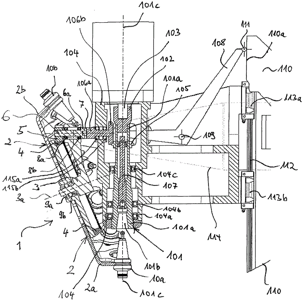
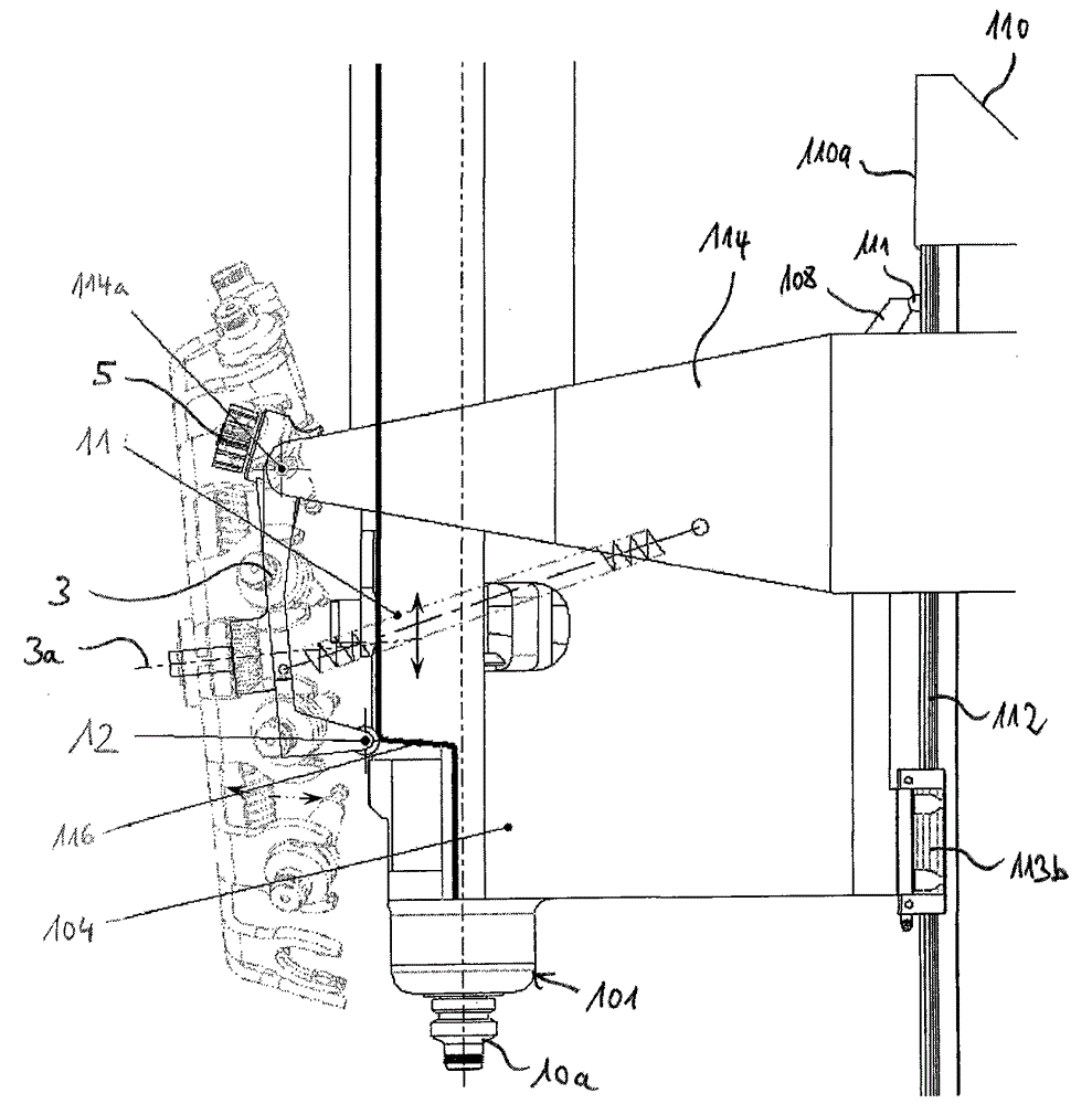
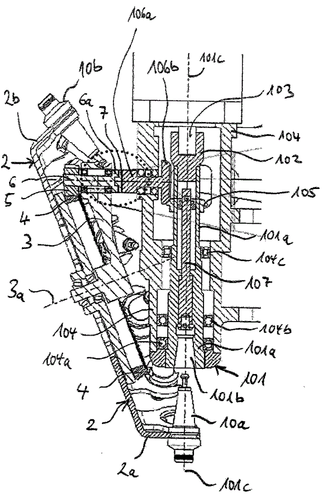
[0050] Preferred embodiments of the present invention will be described below with reference to the accompanying drawings. However, the invention is not limited to the described embodiments. The scope of the present invention is determined by the claims. In the figures, the same or similar features are indicated with the same reference numerals. about figure 2 , 5 and 6, it should be noted that these points mark the ends of these reference lines and should not be understood as technical details of the objects shown. figure 2 , 5 The corresponding reference lines in and 6 with corresponding end points are drawn to be at least partially linear. These at least partially linear reference lines do not represent any technical details of the objects shown. Figure 3A The dots in the dots also do not represent any technical details of the objects shown, but merely illustrate a section of the figure, which is in Figure 3B with 3C Shown in magnified and stereoscopic form.

...


PUM


Abstract

The device has a coupling unit with a coupling element (6) and an oldham coupling having an outer disk (6a) and a middle disk (7), and a gear stage with bevel gears (4) and spur gears (5) for connecting the coupling unit with a tool drum (2). The coupling unit is coupled with another coupling element (106a). Another gear stage has bevel gears (105, 106b) for connecting the latter element with a spindle (101). The drum drives the coupling unit, the elements and the stages to align tool retaining units (2a) when the coupling unit and the elements are coupled with the spindle. An independent claim is also included for a machine tool comprising a tool exchanging device.

Description

technical field [0001] The invention relates to a tool changing device for changing a tool on a spindle of a machine tool, which includes a tool drum, an axle carrier and a transmission device. Wherein the drum tool magazine has a plurality of tool seats arranged along its circumference for holding tools. The drum tool changer is rotatably supported on a spindle frame to align the tool holders with the spindle. Through transmission, the machine spindle drives the drum tool changer to align the tool holders. [0002] Moreover, the present invention also relates to a machine tool, which includes a spindle headstock, a spindle arranged in the spindle headstock, and the above-mentioned tool changing device for replacing a tool on the spindle headstock. Wherein, the drum tool magazine of the tool changing device can be driven by the machine tool spindle through the transmission device to align the tool seat of the drum tool magazine. Background technique [0003] Such tool cha...

Claims


Application Information

Patent Timeline
Patent Type & Authority Patents(China)
IPC IPC(8): B23Q3/155B23Q37/00
CPCY10T483/1795Y10T483/179B23Q3/15706Y10T483/1882B23Q3/15506B23Q3/15534
Inventor 曼纽尔·格斯特迈克尔·伯格拜尔
Owner DMG MORI AG
Learn More