


Quick Research
Generate reliable direction feasibility study reports for your R&D in just a few steps.

Technical Q&A
Discover and master advanced knowledge NOW. Basics, ideas, possibilities, all at once.

Find Solutions
As an expert in R&D theories, this can generate solutions to your technical problems instantly.

Evaluate Feasibility
Analyze your overall solution with one click, know your potential R&D risks in advance.

Monitor Landscape
Get weekly tech updates, stay abreast of the latest tech innovations and key insights.
fiber optic cable
An optical fiber cable and optical fiber technology, applied in the field of optical fiber and cable, can solve problems such as disconnection and fiber damage, and achieve the effect of reducing the possibility of optical fiber disconnection and suppressing loss fluctuations.
- Summary
- Abstract
- Description
- Claims
- Application Information
AI Technical Summary
Problems solved by technology
Method used
Image


Examples
Embodiment
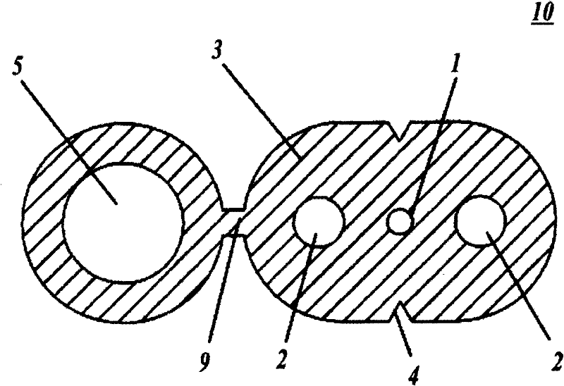
[0074] Using thermoplastic resin to form the sheath 3, manufactured with figure 1 In the same optical fiber cable 10 as shown, the thermoplastic resin can change the stress at the yield point and the 0.3% modulus by adjusting the type (density) of the base polyolefin material and the type / amount of compounded resin or flame-retardant material. , Tensile strength, Shore D. Using these optical fiber cables 10, the average depth of spawning scars, loss variation during spawning, ease of extraction at -20°C, ease of extraction at normal temperature, separation performance of support wires at -20°C, normal temperature The separation performance under the support wire was evaluated.
[0075] In addition, the methods for evaluating the average depth of spawning scars and loss fluctuation during spawning are the same as those described above. In addition, the measurement of the tensile strength was performed at 23° C. using a No. 2 dumbbell sample by a method based on JIS K7113.
...
PUM
 Abstract
Description
Claims
Application Information
 - R&D Engineer
- R&D Manager
- IP Professional
- Industry Leading Data Capabilities
- Powerful AI technology
- Patent DNA Extraction
Browse by: Latest US Patents, China's latest patents, Technical Efficacy Thesaurus, Application Domain, Technology Topic, Popular Technical Reports.
© 2024 PatSnap. All rights reserved.Legal|Privacy policy|Modern Slavery Act Transparency Statement|Sitemap|About US| Contact US: help@patsnap.com