
Clock recovery method for high-speed optical time-division multiplexing system

An optical time division multiplexing and clock recovery technology, applied in time division multiplexing systems, multiplexing communications, electrical components, etc., can solve the problem of difficult to obtain fast locking, restricted applications, and difficult to obtain fast phase Synchronization and other issues, to achieve the effect of fast clock synchronization, simple structure, and stable system

Inactive Publication Date: 2011-11-23
UNIV OF ELECTRONICS SCI & TECH OF CHINA
View PDF3 Cites 11 Cited by
  • Summary
  • Abstract
  • Description
  • Claims
  • Application Information

AI Technical Summary

Problems solved by technology

Since the phase-locked loop is a "memory" system, its output needs a certain amount of time to respond to input changes. Although this method recovers the clock with small jitter and high quality, it is difficult to obtain fast locking, that is, it is difficult to obtain fast phase synchronization of
In addition, with the increase of the multiplexing rate, it is difficult to realize high-rate (>160Gbit / s) electro-optic / all-optical phase detectors, which restricts the application of this method in ultra-high-rate OTDM systems

Method used


Image

  • Clock recovery method for high-speed optical time-division multiplexing system
  • Clock recovery method for high-speed optical time-division multiplexing system
  • Clock recovery method for high-speed optical time-division multiplexing system

Examples


Embodiment Construction

[0020] In order to better understand the technical solution of the present invention, the implementation manner will be further described below in conjunction with the accompanying drawings.

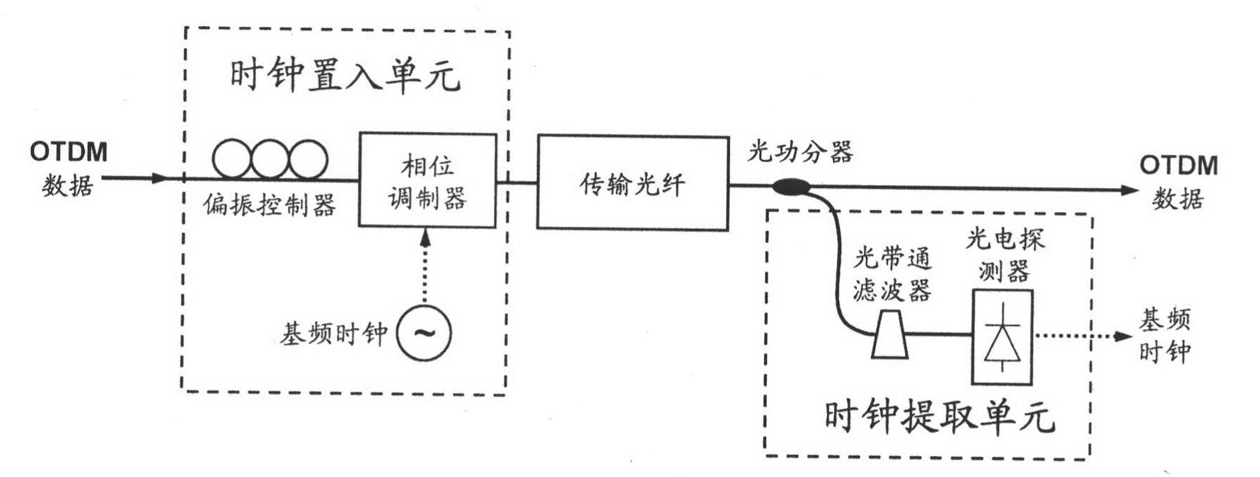
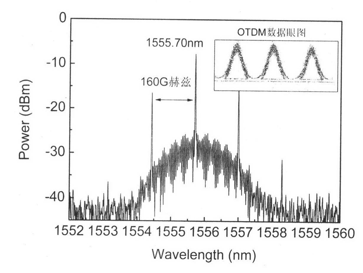
[0021] Such as figure 1 As shown in the basic principle of optical time division multiplexing, the frequency of the base frequency clock in this embodiment is 10G Hz, the high repetition frequency pulse source produces a wavelength of 1550.70nm, a pulse width of 1.4ps, and a repetition frequency of 10G Hz. Frequency optical pulse, after 16 channels of splitting, after each channel is loaded with 10Gbit / s data, the 16 channels of 10Gbit / s data are synthesized after delay, and finally form a 160Gbit / s high-speed data stream output, image 3 Shown is the eye diagram of a 160Gbit / s data signal, Figure 4 The sub-picture in the upper right corner of the 160Gbit / s data signal spectrum.

[0022] Step 1 Clock recovery system composition

[0023] Such as figure 2 As shown, the high-speed dat...


PUM


Abstract

The invention provides a clock recovery method for a high-speed optical time-division multiplexing system. In the method, a base frequency clock is put into a high-speed optical time-division multiplexing data tape in an additional phase modulation manner, so that co-transmission of high-speed optical time-division multiplexing data and the base frequency clock is realized; and base frequency clock recovery of the optical time-division multiplexing system can be realized by only separating the base frequency clock out at a receiving end. According to the method, the defect of the need of the optical phase-locked loop structure for the recovery of a clock from optical time-division multiplexing data streams in the prior art is overcome, and a foundation is laid for the research of a high-speed optical signal processing unit orienting to a next generation all-optical communication network. The method has the characteristics of novel scheme, simple structure and high compatibility, and has extensive application prospects in the aspects of optical fiber communication system, all-optical switch networking, and the like.

Description

technical field [0001] The invention relates to a clock recovery method for an optical time division multiplexing system, in particular, a data and clock co-transmission scheme based on additional phase modulation is designed to realize a method for clock recovery of the optical time division multiplexing system. Background technique [0002] Optical time division multiplexing (OTDM) technology uses ultra-short pulses and return-to-zero codes (RZ) to combine 2 N (N is a positive integer) the base rate B bit / second data communication is mapped to a base frequency clock cycle, and 2 in the time domain N The optical signal of roadbed rate is multiplexed into B×2 N High-speed optical pulse data stream at bit / s rate. After the OTDM signal is transmitted through the optical fiber, the data signal of each road-base rate is recovered through the optical demultiplexer. Compared with the wavelength division multiplexing (WDM) system, OTDM uses a single light source, which avoids th...

Claims


Application Information

Patent Timeline
IPC IPC(8): H04J3/06
Inventor 张尚剑张衎包小斌邹新海刘爽刘永刘永智
Owner UNIV OF ELECTRONICS SCI & TECH OF CHINA
Learn More