Optical signal control method, optical signal control system and optical back plate system
A control method and technology for a control system, applied in the field of optical communication, can solve problems such as optical signal leakage, and achieve the effects of reducing system cost, reducing complexity, and avoiding damage
- Summary
- Abstract
- Description
- Claims
- Application Information
AI Technical Summary
Problems solved by technology
Method used
Image
Examples
Embodiment 1
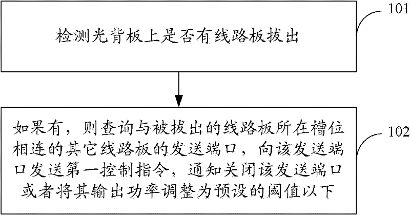
[0029] see figure 1 , this embodiment provides an optical signal control method, the method comprising:
[0030] 101: Detect whether there is a circuit board pulled out from the optical backplane;
[0031] 102: If a circuit board is pulled out, query the sending ports of other circuit boards connected to the slot where the pulled out circuit board is located, and send a first control command to the sending port, and the first control command is used to notify the shutdown of the circuit board. The sending port may adjust the output power of the sending port to be below a preset threshold, where the preset threshold is a specified boundary value for distinguishing whether the sending port is in a working state.
[0032] In this embodiment, there are at least two data slots on the optical backplane, and the data slots include service board slots or switching board slots, one of which is the slot where the circuit board to be pulled out is located, and the other or more It is t...
Embodiment 2
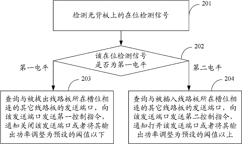
[0045] see figure 2 , this embodiment provides a method for controlling an optical signal, which is controlled based on an in-position detection signal, and the method includes:
[0046] 201: Detect the presence detection signal on the optical backplane.
[0047] 202: Judging whether the presence detection signal is the specified first level, if the presence detection signal is the specified first level, then execute 203; if the presence detection signal is the specified second level, then Execute 204.
[0048] Wherein, the specified first level is a high level, and the second level is a low level; or, the specified first level is a low level, and the second level is a high level.
[0049] 203: Determine that a circuit board has been pulled out from the optical backplane, query the sending ports of other circuit boards connected to the slot where the pulled out circuit board is located, send the first control command to the sending port, and notify to close the sending port...
Embodiment 3
[0072] see Image 6 , this embodiment provides an optical signal control system, the system includes:
[0073] A detection module 601, configured to detect whether a circuit board is pulled out from the optical backplane;
[0074] The control module 602 is used for if the detection module 601 detects that a circuit board is pulled out, then query the sending ports of other circuit boards connected to the slot where the pulled out circuit board is located, and send a first control instruction to the sending port, the The first control instruction is used to notify to close the sending port or adjust the output power of the sending port to be below a preset threshold, where the preset threshold is a specified boundary value for distinguishing whether the sending port is in a working state.
[0075] In this embodiment, there are at least two data slots on the optical backplane, and the data slots include service board slots or switching board slots, one of which is the slot wher...
PUM
 Abstract
Description
Claims
Application Information
 - Generate Ideas
- Intellectual Property
- Life Sciences
- Materials
- Tech Scout
- Unparalleled Data Quality
- Higher Quality Content
- 60% Fewer Hallucinations
Browse by: Latest US Patents, China's latest patents, Technical Efficacy Thesaurus, Application Domain, Technology Topic, Popular Technical Reports.
© 2025 PatSnap. All rights reserved.Legal|Privacy policy|Modern Slavery Act Transparency Statement|Sitemap|About US| Contact US: help@patsnap.com


