
Heat-insulation ceiling lamp

A technology for lamps and ceilings, applied in the field of lighting, can solve problems such as the difficulty of covering the surface of lamps with laminating materials, the inability to meet the low temperature of the surface of lamps, and the failure to reach a temperature lower than 90 degrees, so as to ensure safety, overall appearance, and good sound insulation. Effect

Inactive Publication Date: 2011-11-23
武良举
View PDF2 Cites 1 Cited by
  • Summary
  • Abstract
  • Description
  • Claims
  • Application Information

AI Technical Summary

Problems solved by technology

When the luminaire is covered with insulating material, the situation is even worse, the temperature of the surface of the luminaire will be much higher, and the existing fireproof luminaires have many hidden dangers of causing fire
Accordingly, the operating temperature of the existing ceiling lamps is too high, failing to meet the requirements of the standard
Although some fire-resistant lamps will be equipped with fire-resistant materials to achieve the purpose of fire-proof and heat-insulation, this purpose refers to the fire-proof and heat-insulation in case of fire, and it is not set to meet the requirement that the surface temperature of the lamp is lower than 90 degrees, and the test found that such The structure of the lamp cannot meet the requirement that the temperature is lower than 90 degrees, and it is very difficult to cover the surface of the lamp with bonding materials, because the fireproof materials are generally flakes, which need to be cut and bonded seamlessly.
For some European countries such as the United Kingdom and Denmark, the requirements for ceiling lamps are not only in terms of fire performance, but also in the safety performance of lamps. The requirements for the surface temperature of lamps are higher, and simple installation of fireproof materials cannot meet the requirements. Requirements for low temperature on the surface of lamps

Method used


Image

  • Heat-insulation ceiling lamp
  • Heat-insulation ceiling lamp
  • Heat-insulation ceiling lamp

Examples


Embodiment 1

[0033] see Figure 4, Embodiment 1 of the heat-insulating ceiling lamp of the present invention, the shell of the heat-insulating ceiling lamp includes a tube cover 1 and a flange 2 located below the tube cover, the tube cover and the flange are both provided with a double-layer sealing structure 3, and the double-layer sealing structure 3 is provided. There is a cavity in the double-layer sealing structure, and the cavity is a vacuum structure, and the cavity in the double-layer sealing structure between the cylinder cover and the flange is connected.

[0034] In this embodiment, the outlet hole 4 on the top of the tube cover is designed to be sealed around, and the ceiling lamp is a sealed structure as a whole, which has the effects of heat preservation, heat insulation, and flame retardancy, and can block the loss of useful air in the room, and has the effect of sound insulation , the overall appearance is beautiful, and the production process is simple. And this tube cove...


PUM


Abstract

The invention discloses a heat-insulation ceiling lamp which comprises a shell and a lamp holder used for installing a bulb, wherein the shell comprises a cylinder cover and a flange positioned below the cylinder cover, the cylinder cover and / or the flange are / is of a double-layer sealing structure, the double-layer sealing structure is provided with a cavity, and the cavity is of a vacuum structure; and the ceiling lamp is of an internally-evacuated double-layer sealing structure, thereby ensuring the interior of the lamp to heat, wherein the heat is separated instead of being delivered to the outer surface of the lamp, the internally-evacuated double-layer sealing structure has a heat-insulation effect, the temperature of the outer surface of the ceiling lamp can be maintained in a low-temperature state, the safety of the lamp operating environment is ensured, and the safety requirements of the lamp design and installation are met.

Description

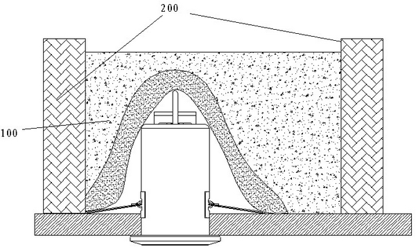
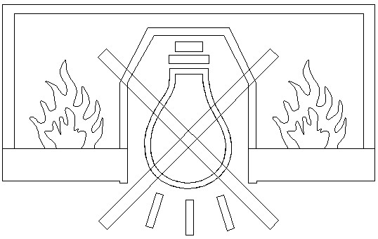
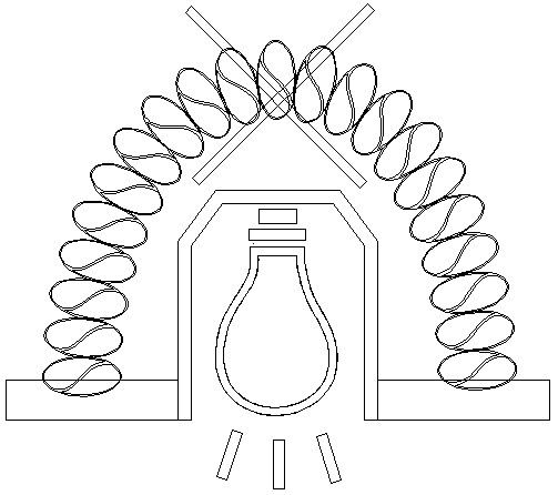
[0001] 【Technical field】 [0002] The invention relates to the field of lighting, in particular to a ceiling lamp embedded in a ceiling with heat insulation performance. [0003] 【Background technique】 [0004] Recessed ceiling lamps are generally used in modern interior design and decoration, home lighting, office lighting and other occasions. The most common application of recessed ceiling lamps is to install them in the openings that have been opened on the ceiling. Combustible materials such as wood and plastic, etc., if a recessed ceiling lamp is installed on the ceiling, the bulb in the lamp may ignite the ceiling due to excessive temperature. In addition, the tube cover of the lamp is embedded in the space behind the ceiling. In this space behind the ceiling, there are generally some building insulation materials, such as glass fiber, ceramic fiber, aluminum silicate, etc., such as figure 1 As shown, these building insulation materials 100 are covered around and on ...

Claims


Application Information

Patent Timeline
Patent Type & Authority Applications(China)
IPC IPC(8): F21S8/04F21V15/02F21V25/12F21V29/00F21V29/83
Inventor 武良举
Owner 武良举
Learn More