
Two-phase vacuum suction system, and method for treating petroleum pollutants by using two-phase vacuum suction system

A vacuum suction system and technology for pollutants, which are applied in separation methods, grease/oily substances/float removal devices, liquid separation, etc. The effect of saving running costs and simple operation

Inactive Publication Date: 2011-11-23
NORTH CHINA ELECTRIC POWER UNIV (BAODING)
View PDF4 Cites 3 Cited by
  • Summary
  • Abstract
  • Description
  • Claims
  • Application Information

AI Technical Summary

Problems solved by technology

The consequence of this is that once the repair system stops operating, the bound non-aqueous liquid will continue to be discharged into the water body as a persistent pollution source, thus polluting the water body again
The characteristic of oil pollution has led to the incomplete pollution remediation technology commonly used in the world. The new challenge we face is to develop new remediation technologies

Method used

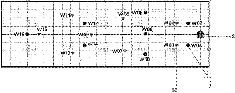
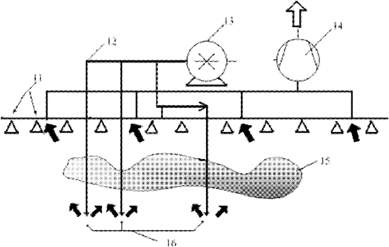

Image

  • Two-phase vacuum suction system, and method for treating petroleum pollutants by using two-phase vacuum suction system
  • Two-phase vacuum suction system, and method for treating petroleum pollutants by using two-phase vacuum suction system
  • Two-phase vacuum suction system, and method for treating petroleum pollutants by using two-phase vacuum suction system

Examples


Embodiment Construction

[0021] The present invention will be further described below in conjunction with the accompanying drawings and specific embodiments.

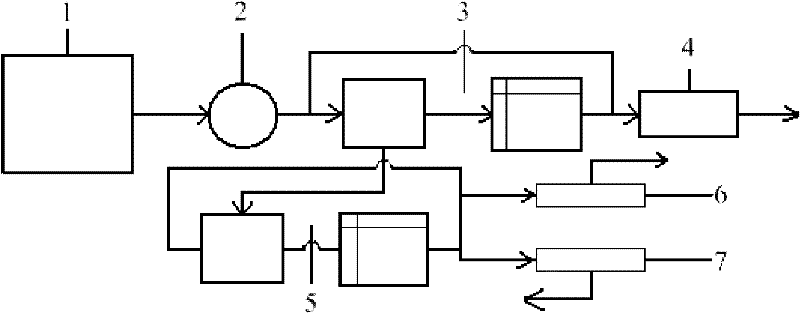
[0022] A two-phase vacuum pumping system such as figure 1 As shown, the system consists of a gas-liquid two-phase vacuum extraction device 1, a transfer pump 2, a primary separator and its controller 3, an exhaust gas recovery device 4, a secondary separator and its controller 5, a waste oil recovery device 6, The waste water return device 7 is composed; the two-phase vacuum extraction device 1 is connected to the transfer pump 2; the transfer pump 2 is connected to the primary separator and its controller 3; the primary separator and its controller 3 are separated from the waste gas recovery device 4 and the secondary The separator and its controller 5 are connected; the secondary separator and its controller 5 are respectively connected with the waste oil recovery device 6 and the waste water return device 7 .

[0023] The two-phase vacuum e...


PUM


Abstract

The invention belongs to the technical field of recovery of petroleum polluted environment, and discloses a vacuum suction system, and a method for treating petroleum pollutants by the vacuum suction system. The system comprises a gas-liquid two-phase vacuum suction apparatus, a transmission pump, a primary separator and a controller thereof, a waste gas recovery apparatus, a secondary separator and a controller thereof, a waste oil recovery apparatus and a waste water reflowing apparatus. The method provided by the present invention is characterized in that: the negative pressure is adopted to suck the petroleum pollutants in pumping wells of the gas-liquid two phase vacuum suction apparatus, and suck the petroleum pollutants to the ground surface; the petroleum pollutants are separated through sequentially passing the primary separator and the secondary separator; the separated gas-phase pollutant, the separated oil-phase pollutant and the water-phase pollutant respectively enter in the waste gas recovery apparatus, the waste oil recovery apparatus and the waste water recovery apparatus to complete the treatment for the petroleum pollutants. With the present invention, the method provided by the present invention is applicable for removing the petroleum pollutants existing in various forms in the underground layer; effluent quality is good; petroleum pollutant removing efficiency is more than 98%; each main contamination index meets national integrated wastewater discharge primary standard.

Description

technical field [0001] The invention belongs to the technical field of oil-polluted environment restoration, and in particular relates to a vacuum suction system and a method for treating oil pollutants. Background technique [0002] The pollution of petroleum and its products to the environment is becoming more and more serious, which has endangered human health and survival. More and more attention has been paid to oil pollution control, relevant control measures and policies have been introduced, and many oil pollution control technologies and methods have emerged. Before the 1980s, the treatment of petroleum hydrocarbon-contaminated soil was limited to physical and chemical methods, namely heat treatment and chemical leaching. Heat treatment is through incineration or calcination, which can purify most of the organic pollutants in the soil, but at the same time, it also destroys the soil structure and components, and is expensive and difficult to implement. Chemical le...

Claims


Application Information

Patent Timeline
Patent Type & Authority Applications(China)
IPC IPC(8): C02F1/40
Inventor 何理黄国和张晓东
Owner NORTH CHINA ELECTRIC POWER UNIV (BAODING)
Learn More