
Dynamic maintenance method and system for storage virtualization

A storage virtualization and virtualization technology, applied in the field of virtual storage, can solve the problems of inconvenient equipment maintenance and cumbersome manual configuration, and achieve the effect of easy management and maintenance

Inactive Publication Date: 2011-11-16
NEW H3C TECH CO LTD
View PDF3 Cites 4 Cited by
  • Summary
  • Abstract
  • Description
  • Claims
  • Application Information

AI Technical Summary

Problems solved by technology

Since the development of cloud storage inevitably requires the integration of a large number of storage devices, this manual configuration method is obviously not convenient for device maintenance; and when each device is owned by different managers, static manual configuration is more cumbersome

Method used


Image

  • Dynamic maintenance method and system for storage virtualization
  • Dynamic maintenance method and system for storage virtualization
  • Dynamic maintenance method and system for storage virtualization

Examples


Embodiment 1

[0037] like Figure 4 It is a flowchart of a dynamic maintenance method for storage virtualization according to Embodiment 1 of the present invention. This embodiment is applicable to the situation where the virtualization device and the storage device are in the same IP network segment. After you have pre-set up multiple zones in your virtualized network, and virtualized and storage devices in each zone, perform the following steps:

[0038] Step 401: The storage device periodically sends a multicast Hello (Hello) message, and the multicast Hello message includes information such as the area identifier of the area where the storage device is located, the IP address of the storage device, and the like;

[0039] At the same time, the virtualization device periodically sends a multicast probe (Probe) message, and the multicast Probe message includes an area identifier of the area where the virtualization device is located, for detecting storage devices in the area;

[0040] Af...

Embodiment 2

[0054] like Figure 5 It is a flowchart of a dynamic maintenance method for storage virtualization according to Embodiment 2 of the present invention. This embodiment is applicable to the situation that the virtualization device and the storage device are in different IP network segments. In this case, since multicast messages cannot pass through routers and cannot be forwarded between different IP network segments, a proxy server needs to be set up in the network. The role of the proxy server is to receive the registration from the storage device, receive the query from the virtualization device, and perform matching detection on the virtualization device and the storage device; both the storage device and the virtualization device need to pre-configure the address of the proxy server.

[0055] After you have pre-set up multiple zones in your virtualized network, and virtualized and storage devices in each zone, perform the following steps:

[0056] Step 501: The storage de...


PUM


Abstract

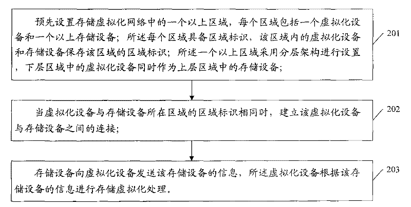
The invention provides a dynamic maintenance method and system for storage virtualization, wherein the dynamic maintenance method comprises the following steps of presetting more than one region in a storage virtualization network, wherein each region comprises a virtualization device and more than one storage device, and each region is provided with a regional identification; storing the regional identification of the region by the virtualization device and the more than one storage device in the region; setting the more than one region by adopting a layered framework, and taking a virtualization device at the lower region as the storage device of the upper region; establishing the connection between the virtualization device and the storage devices when the regional identifications of the regions where the virtualization device and the storage devices are positioned are same; and sending the information of the storage devices to the virtualization device by the storage devices connected with the virtualization device, and carrying out the virtualization process by the virtualization device according to the information of the storage devices. According to the invention, dynamic maintenance can be carried out on the devices in a virtualization plan so that the maintenance process is more convenient.

Description

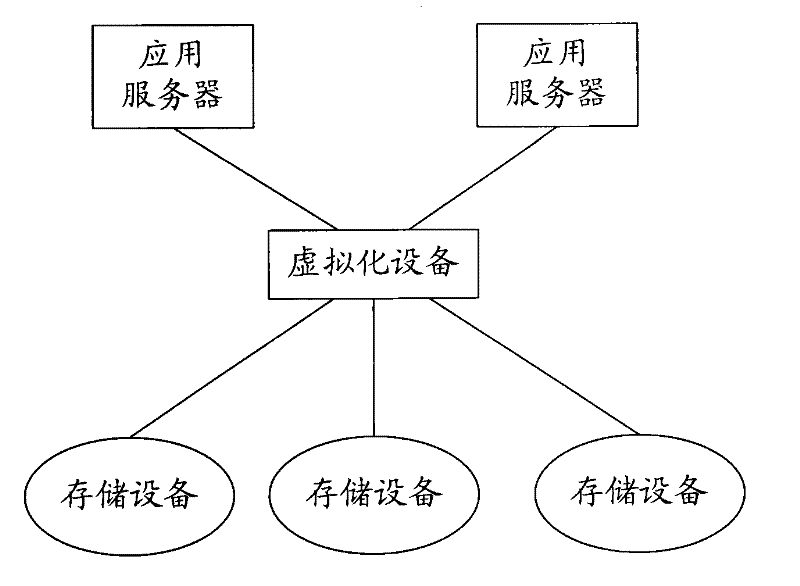
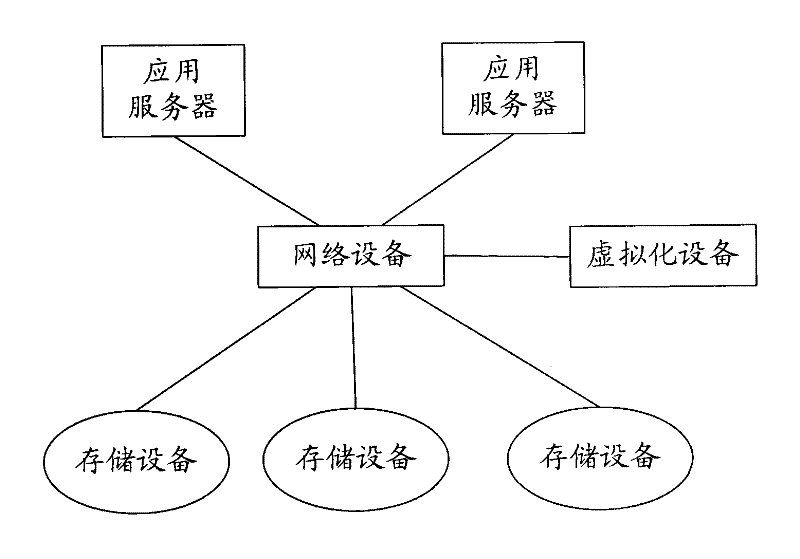
technical field [0001] The invention relates to the technical field of virtual storage, in particular to a dynamic maintenance method and system for storage virtualization. Background technique [0002] The storage virtualization solution is an important technical solution for cloud storage. The storage virtualization solution enables different storage technologies and different interface technologies to be managed uniformly by the virtualization device. The user device only needs to initiate a request to the virtualization device, and the virtualization Devices are coordinated uniformly without requiring specific information about each storage device, simplifying management. [0003] Storage virtualization currently has two major solutions: in-band virtualization and out-of-band virtualization. like Figure 1A is a schematic structural diagram of an in-band virtualization solution in the prior art, Figure 1B It is a schematic structural diagram of an out-of-band virtuali...

Claims


Application Information

Patent Timeline
Patent Type & Authority Applications(China)
IPC IPC(8): H04L29/06H04L29/08H04L12/24
CPCG06F11/2066G06F3/0662G06F17/30067H04L67/1097G06F3/0607G06F3/067G06F9/50H04L29/08549G06F11/2094
Inventor 周迪夏飞
Owner NEW H3C TECH CO LTD
Learn More