
Acousto-optic Q-switched high-power pulse fiber laser

A fiber laser, high-power pulse technology, applied in the laser field, can solve problems such as narrowing of spectral bandwidth, poor temperature stability, and fiber burnout

Inactive Publication Date: 2011-11-16
MAXPHOTONICS CORP
View PDF4 Cites 6 Cited by
  • Summary
  • Abstract
  • Description
  • Claims
  • Application Information

AI Technical Summary

Problems solved by technology

[0003] However, this kind of pulsed fiber laser using FBG as a high-reflection mirror has poor temperature stability. When the environment changes, the central wavelength of the FBG is prone to drift, and the high-reflection grating and the low-reflection grating are easily mismatched, resulting in the laser spectrum. The bandwidth narrows, and in the case of a certain pulse peak power, it is easy to generate nonlinear stimulated Brillouin scattering SBS, which will generate extremely high peak power after amplification in the latter stage, which will easily cause fiber burnout. This is the current domestic and foreign regulation. The root cause of the poor reliability of Q pulsed fiber lasers, according to statistics, the repair rate of pulsed fiber lasers produced abroad is about 10%, and the repair rate of using FBG for high reflection is about 70% to 10%.
[0004] In summary, the existing acousto-optic Q-switched high-power pulsed fiber lasers obviously have inconvenience and defects in actual use, so it is necessary to improve them

Method used


Image

  • Acousto-optic Q-switched high-power pulse fiber laser
  • Acousto-optic Q-switched high-power pulse fiber laser
  • Acousto-optic Q-switched high-power pulse fiber laser

Examples


Embodiment Construction

[0029] In order to make the object, technical solution and advantages of the present invention clearer, the present invention will be further described in detail below in conjunction with the accompanying drawings and embodiments. It should be understood that the specific embodiments described here are only used to explain the present invention, not to limit the present invention.

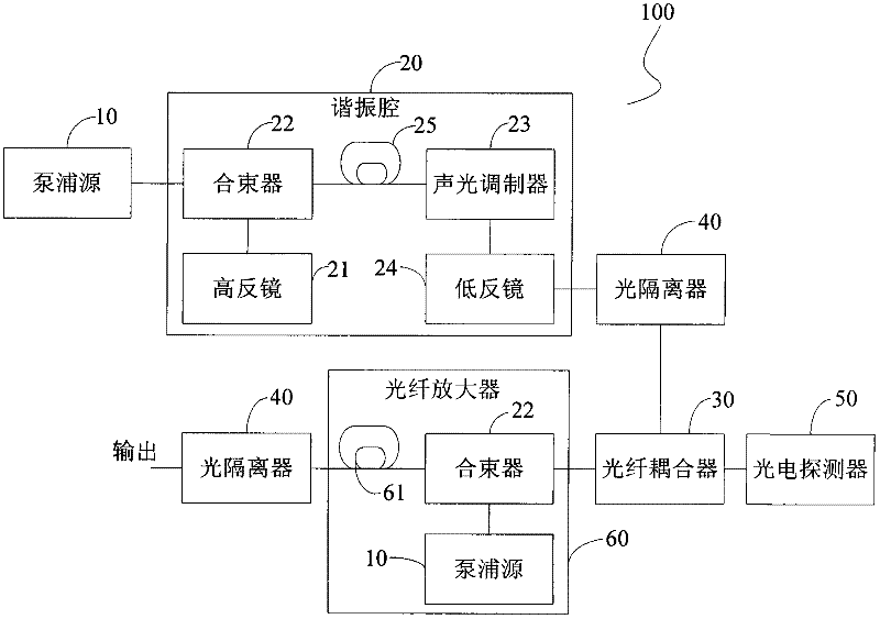
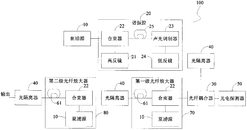
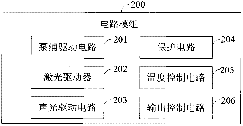
[0030] see figure 1 and image 3 , the present invention provides an acousto-optic Q-switched high-power pulsed fiber laser, which includes an optical path module 100 and a circuit module 200, the optical path module 100 is used for conversion and transmission of laser signals, and the circuit module 200 is used for providing Each fiber optic component of module 100 provides actuation. Specifically, the optical path module 100 includes:

[0031] The pumping source 10 is used to generate the pumping laser, which includes several pumping lasers. For the convenience of description, the number of pu...


PUM

PropertyMeasurementUnit
Reflection bandwidthaaaaaaaaaa

Abstract

The invention discloses an acousto-optic Q-switched high-power pulse fiber laser, which comprises a light path module and a circuit module. The light path module comprises a pump source, a resonant cavity and a fiber optic amplifier, wherein the pump source is used for generating pumped laser, and comprises a plurality of pump lasers; the resonant cavity is used for converting the pumped laser into pulse laser; a high reflective mirror and an acousto-optic modulator are arranged in the resonant cavity, and the resonant cavity is connected to the pump source; and the fiber optic amplifier is used for performing power amplification on the pulse laser and outputting the amplified pulse laser. Preferably, the high reflective mirror adopted by the laser has the reflected bandwidth capable of reaching 100nm and the reflectivity of 99 percent, and can bear the peak power of dozens of kilowatts and the average power of dozens of watts. Therefore, the laser solves the problem that the spectral bandwidth of the output laser is narrowed under the condition of certain pulse peak power, can avoid the nonlinear stimulated Brillouin scattering (SBS) of the laser, and has high reliability.

Description

technical field [0001] The invention relates to the field of laser technology, in particular to an acousto-optic Q-switched high-power pulse fiber laser. Background technique [0002] With the development of laser technology, laser processing has gradually become popular, and in laser processing, fiber lasers play an irreplaceable role. At present, there are pulsed fiber lasers in the world. The technical solution adopted is to use a fiber grating (FBG) with a broadband of about a few tenths of a nanometer as the high mirror of the resonator, and use a fiber grating with a bandwidth of a few tenths of a nanometer with a relatively low reflectivity as the resonant cavity. Low-reflection mirror, use fiber-coupled acousto-optic Q switch Q-switching in the resonator to generate light pulses on the order of tens of nanoseconds to hundreds of nanoseconds as the seed source, and then pass through the first or second double-clad fiber After being amplified by the amplifier, light p...

Claims


Application Information

Patent Timeline
IPC IPC(8): H01S3/139
Inventor 胡小波
Owner MAXPHOTONICS CORP
Learn More