Contact hole and semiconductor device as well as formation method of contact hole and semiconductor device

A technology of contact holes and substrates, applied in semiconductor devices, semiconductor/solid-state device manufacturing, semiconductor/solid-state device components, etc.

Active Publication Date: 2011-11-16
INST OF MICROELECTRONICS CHINESE ACAD OF SCI
View PDF2 Cites 8 Cited by
  • Summary
  • Abstract
  • Description
  • Claims
  • Application Information

AI Technical Summary

Problems solved by technology

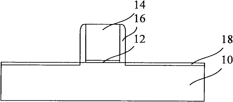
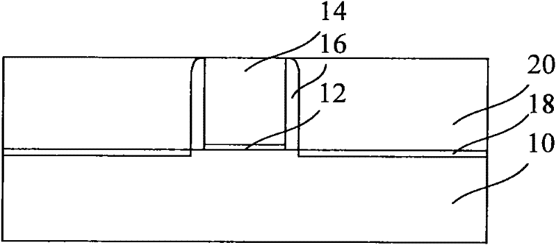
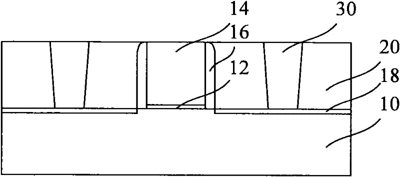
[0004] It can be seen that when using the above method to etch the interlayer dielectric layer 20 to form the contact hole 30, a mask is necessary, but with the reduction of the size of the contact hole 30, the application of the mask may not necessarily Obtain the contact hole 30 that satisfies the process requirements, that is, this mask may not realize its due effect, therefore, how to remove the mask to form a contact hole becomes the main problem solved by the present invention

Method used


Image

  • Contact hole and semiconductor device as well as formation method of contact hole and semiconductor device
  • Contact hole and semiconductor device as well as formation method of contact hole and semiconductor device
  • Contact hole and semiconductor device as well as formation method of contact hole and semiconductor device

Examples


Embodiment Construction

[0052] The disclosure below provides many different embodiments or examples for realizing the technical solution provided by the present invention. Although components and arrangements of specific examples are described below, they are examples only and are not intended to limit the invention.

[0053] Furthermore, the present invention may repeat reference numerals and / or letters in different embodiments. This repetition is for simplicity and clarity and does not in itself indicate a relationship between the various embodiments and / or arrangements discussed.

[0054] The present invention provides examples of various specific processes and / or materials, however, alternative applications of other processes and / or other materials that can be realized by those skilled in the art obviously do not depart from the scope of the present invention. It should be emphasized that the boundaries of various regions described in this document include necessary extensions due to process or ...


PUM


Abstract

The invention discloses a formation method of a contact hole. The method comprises the following steps: forming a grid electrode, a side wall, a sacrificial side wall, a source region and a drain region on a substrate, wherein the side wall surrounds the grid electrode; the sacrificial side wall covers the side wall; and the source region and the drain region are embedded in the substrate and are positioned at two sides of the grid electrode; forming an interlayer medium layer, thus the interlayer medium layer exposes the grid electrode, the side wall and the sacrificial side wall; removing the sacrificial side wall to form a contact space, wherein the material of the sacrificial side wall is different from materials of the grid electrode, the side wall and the interlayer medium layer; forming an electric conduction layer, wherein the electric conduction layer fills the contact space; and disconnecting the electric conduction layer to form at least two electric conductors, and each conductor is respectively connected to the source region or the drain region. The invention also discloses the contact hole. The contact hole, the grid electrode and the side wall are formed on the substrate and are embedded in the interlayer medium layer, and the side surface of the contact hole is connected to the side wall. The invention also discloses a semiconductor device and a formation method thereof. According to the invention, the number of applied masks can be reduced.

Description

technical field [0001] The invention relates to the technical field of semiconductors, in particular to a contact hole, a semiconductor device and a method for forming the two. Background technique [0002] As the critical dimensions of semiconductor devices gradually decrease, various microscopic effects begin to appear, the manufacturing process of semiconductor devices becomes more and more complex, and it becomes more and more difficult to optimize the performance of semiconductor devices. Complex manufacturing processes require more masks and multi-step photolithography processes, and how to improve the manufacturing process of contact holes has become a challenging and practical research direction for optimizing the performance of semiconductor devices. [0003] Specifically, the existing methods for forming contact holes include: figure 1 As shown, a gate 14 and a spacer 16 are formed on a substrate 10, the gate 14 is formed on the substrate 10 via a gate dielectric ...

Claims


Application Information

Patent Timeline
Patent Type & Authority Applications(China)
IPC IPC(8): H01L21/768H01L21/8234H01L21/28H01L23/532
CPCH01L29/6653H01L21/76897H01L21/76831H01L29/41783H01L29/6656
Inventor 钟汇才梁擎擎
Owner INST OF MICROELECTRONICS CHINESE ACAD OF SCI
Why Eureka
Try Eureka