Switch control circuit

A switch control circuit and control chip technology, which is applied in the direction of electrical components, output power conversion devices, etc., can solve the problem of fast opening and closing speeds of IGSFETs, electromagnetic interference, and voltage spikes at the closing speed of IGSFETs And other issues

Inactive Publication Date: 2011-11-09
HONG FU JIN PRECISION IND (SHENZHEN) CO LTD +1
View PDF5 Cites 1 Cited by
  • Summary
  • Abstract
  • Description
  • Claims
  • Application Information

AI Technical Summary

Problems solved by technology

However, the turn-on and turn-off speeds of existing insulated gate field effect transistors are relatively fast.
In addition, in the switch control circuit, if the closing speed of the IGSFET is too fast, a voltage spike will be generated, causing electromagnetic interference

Method used


Image

  • Switch control circuit
  • Switch control circuit

Examples


Embodiment Construction

[0029] Below in conjunction with accompanying drawing and preferred embodiment the present invention is described in further detail:

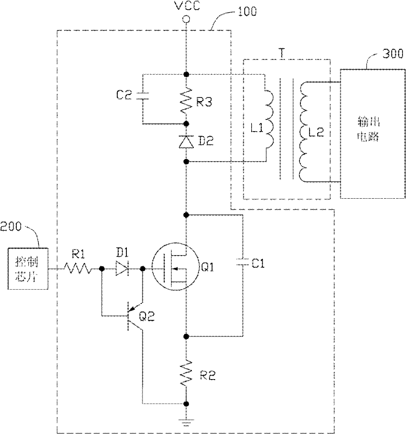
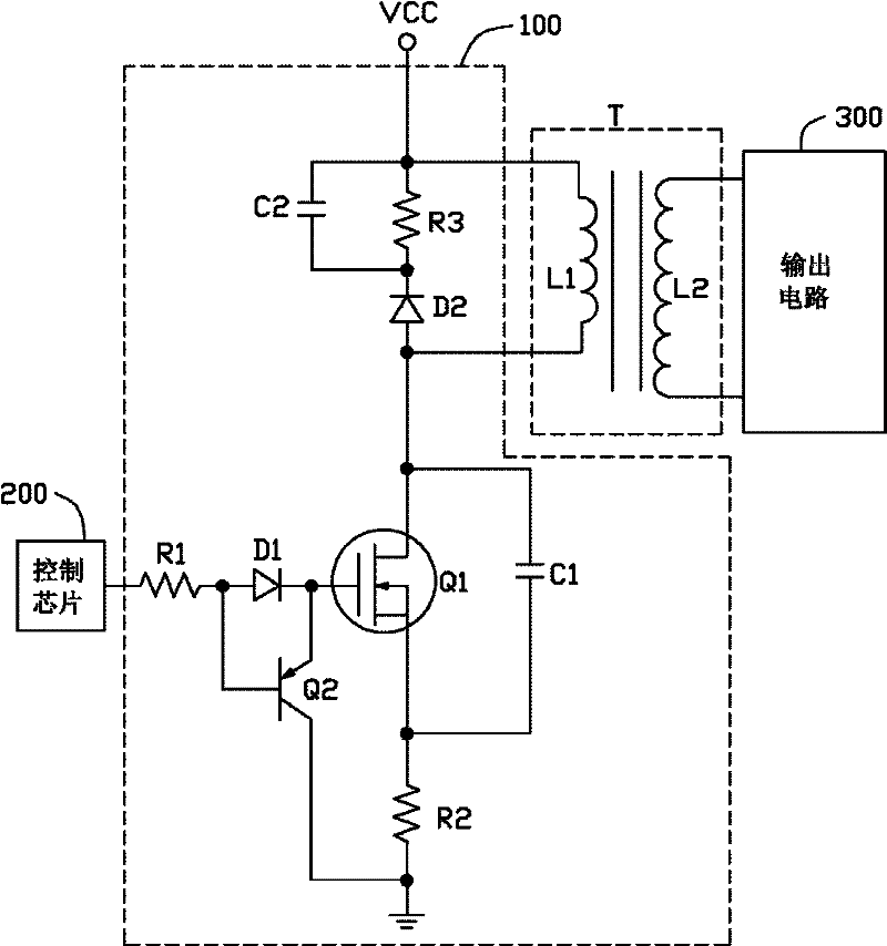
[0030] Please refer to figure 1 , the switching control circuit 100 of the present invention is connected between a control chip 200 and a switching transformer T, and the switching transformer T is also connected to an output circuit 300 . The switch control circuit 100 is used to control whether the voltage of a power supply VCC is transformed by the switching transformer T and then output to the back-end components (not shown) through the output circuit 300 .

[0031] The switch control circuit 100 includes an IGSFET Q1, a PNP transistor Q2, a first diode D1, a second diode D2, resistors R1-R3, and capacitors C1-C2. In this implementation manner, the IGSFET Q1 is an N-type IGSFET.

[0032] The anode of the first diode D1 is connected to the control chip 200 through the resistor R1, and is also connected to the base of the PNP transistor Q2...


PUM


Abstract

The invention discloses a switch control circuit, which comprises a PNP (Positive Negative Positive) type triode, an insulated gate field effect tube, a first diode, a second diode, a first resistor, a second resistor, a third resistor and a first capacitor, wherein the base of the PNP type triode is connected with the anode of the first diode; the emitter of the PNP type triode is connected with the cathode of the first diode; the gate of the insulated gate filed effect tube is connected with the cathode of the first diode; and the drain of the insulated gate filed effect tube is connected with the anode of the second diode. The starting speed of the switch control circuit is lowered through the first resistor and the first diode tube, and the shut-down speed of the switch control circuit is increased by using the PNP type triode.

Description

technical field [0001] The invention relates to a switch control circuit. Background technique [0002] Field effect transistors are often used in switch control circuits. The switching action of the ideal field effect tube is: the opening speed is slow, and the closing speed is fast. However, the turn-on and turn-off speeds of the existing IGSFETs are relatively fast. In addition, in the switch control circuit, if the closing speed of the IGSFET is too fast, a voltage spike will be generated, which will cause electromagnetic interference. Contents of the invention [0003] In view of the above, it is necessary to provide a switch control circuit with a slow turn-on speed and a fast turn-off speed without causing electromagnetic interference. [0004] A switch control circuit, comprising: [0005] a first resistor; [0006] A first diode, the anode of which is connected to a control chip through the first resistor, and the control chip is used to output a high level s...

Claims


Application Information

Patent Timeline
IPC IPC(8): H02M1/36
Inventor 王进波
Owner HONG FU JIN PRECISION IND (SHENZHEN) CO LTD
Why Eureka
Try Eureka