Laser interference lithographic system

A laser interference lithography and photolithography technology, applied in the field of micro-nano structure manufacturing, can solve the problems of small adjustment range of interference beam angle, limited interference pattern diversity, complex optical path system, etc., to reduce optical path loss, meet the diversity, The effect of increasing the adjustment range

Active Publication Date: 2011-11-09
SUZHOU UNIV
View PDF6 Cites 8 Cited by
  • Summary
  • Abstract
  • Description
  • Claims
  • Application Information

AI Technical Summary

Problems solved by technology

[0005] However, the laser interference lithography system in the prior art has the following disadvantages: one is that the beam splitter of the system is far away from the main optical axis, and the optical path system is relatively complicated; the other is that the system is connected to the driving device in order to avoid blocking the incident light The wheel 2 is designed in a fan shape, resulting in a small adjustment range of the interference beam angle, which limits the diversity of interference patterns

Method used


Image

  • Laser interference lithographic system
  • Laser interference lithographic system
  • Laser interference lithographic system

Examples


Embodiment 1

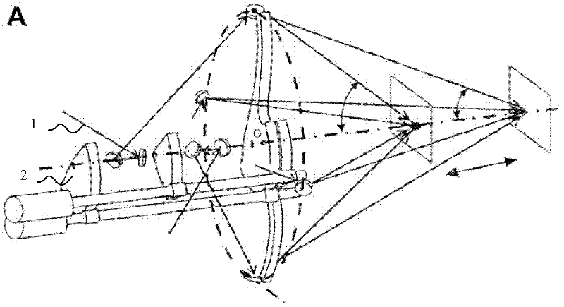
[0039] see image 3 , is a structural diagram of a laser interference lithography system disclosed in Embodiment 1 of the present invention. like figure 1 As shown, the system includes: four mirror groups. The first mirror group comprises: beam splitter 1011, the first total reflection mirror 1012 and the second total reflection mirror 1013; the second mirror group comprises: beam splitter 1021, the first total reflection mirror 1022 and the second total reflection mirror 1023; the third The mirror group includes: a beam splitter 1031 , a first total reflection mirror 1032 and a second total reflection mirror 1033 ; the fourth mirror group includes: a beam splitter 1041 , a first total reflection mirror 1042 and a second total reflection mirror 1043 .

[0040] The beam splitters of each mirror group are located on the main optical axis of the incident light. The first lens group to the fourth lens group are sequentially arranged on the main optical axis in order of distance...

Embodiment 2

[0057] see Figure 4 , is a structural diagram of the laser interference lithography system disclosed in Embodiment 2 of the present invention. like Figure 4 As shown, the system includes: a first type-one mirror group composed of a beam splitter 2011, a total reflection mirror 2012 and a total reflection mirror 2013; a second type-one mirror group composed of a beam splitter 2021, a total reflection mirror 2022 and a total reflection mirror 2023 The third one-type mirror group that beam splitter 2031, total reflection mirror 2032 and total reflection mirror 2033 constitute; the second type mirror group that total reflection mirror 2041,2042,2043 forms.

[0058] Wherein, the beam splitter 2011 of the first type I mirror group, the beam splitter 2021 of the second type I mirror group, the beam splitter 2031 of the third type I mirror group and the total reflection mirror 2041 of the second type mirror group are all positioned at the center of the incident light on the princi...


PUM


Abstract

The invention discloses a laser interference lithographic system, which comprises at least two lens groups. The lens group comprises a beam splitter, a first completely reflecting mirror and a second completely reflecting mirror. The beam splitter of the lens group is positioned on the main optical axis of incident light. Different lens groups are positioned at different positions of the main optical axis. After passing through the beam splitter of each lens group, the incident light generates reflected light and transmitted light, wherein the reflected light irradiates interference points of a sample to be lithographed after being reflected by the first and second completely reflecting mirrors of the current lens group; and the transmitted light is taken as the incident light of the lens group adjacent to the current lens group. In the laser interference lithographic system provided by the invention, angles of incident planes of interference light can be randomly adjusted about the main optical axis of the incident light so as to greatly widen the adjustment range of the angles of the incident planes of the interference light and meet the diversity of interference patterns.

Description

technical field [0001] The invention relates to the field of micro-nano structure manufacturing, in particular to a laser interference lithography system. Background technique [0002] Surface periodic micro-nano structure, as a cutting-edge technology, has shown attractive application prospects in many fields, such as anti-reflection, light trapping, waterproof self-cleaning, photonic crystals, etc. The methods for making such surface periodic micro-nano structures usually include electron beam etching and nanoimprint lithography, but these two methods are often costly and expensive, and cannot be prepared in a large area or the prepared surface structure is not fine enough; and Laser interference lithography can produce surface periodic micro-nano structures in a large area at a lower cost. [0003] The basic principle of laser interference lithography is to use two or more beams of coherent laser beams to superimpose and irradiate the surface of the sample to generate an...

Claims


Application Information

Patent Timeline
Patent Type & Authority Applications(China)
IPC IPC(8): G03F7/20G02B7/00
Inventor 彭长四董晓轩张伟顾小勇周云刘维萍
Owner SUZHOU UNIV
Why Eureka
Try Eureka