Machine tool
A machine tool and bed technology, applied in the field of mechanical equipment, can solve problems such as single function, and achieve the effect of easy planing and grinding
- Summary
- Abstract
- Description
- Claims
- Application Information
AI Technical Summary
Problems solved by technology
Method used
Image

Examples
Embodiment 1
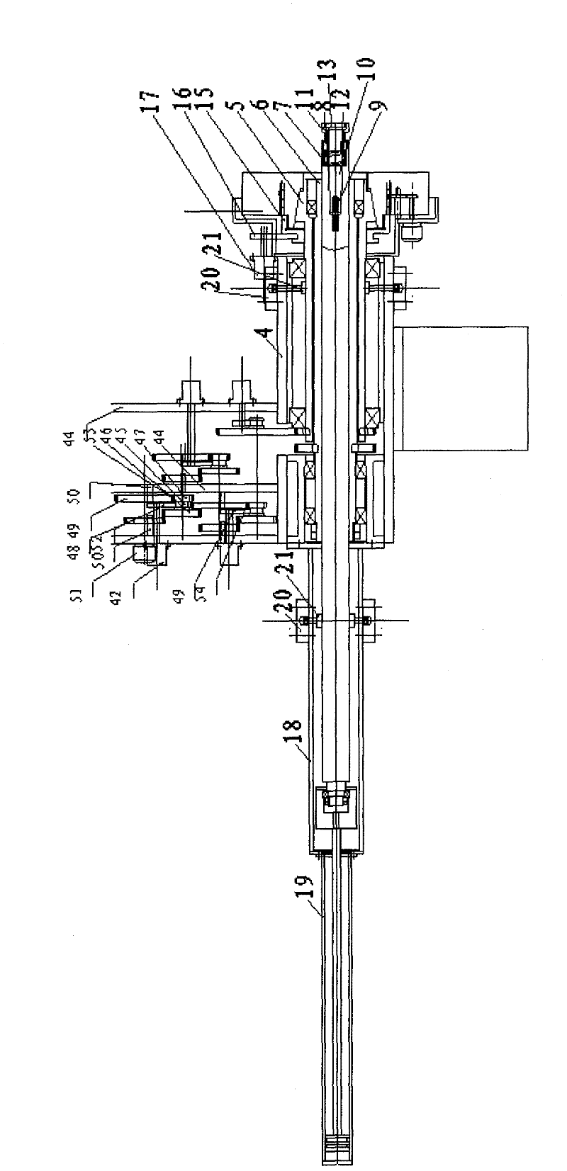
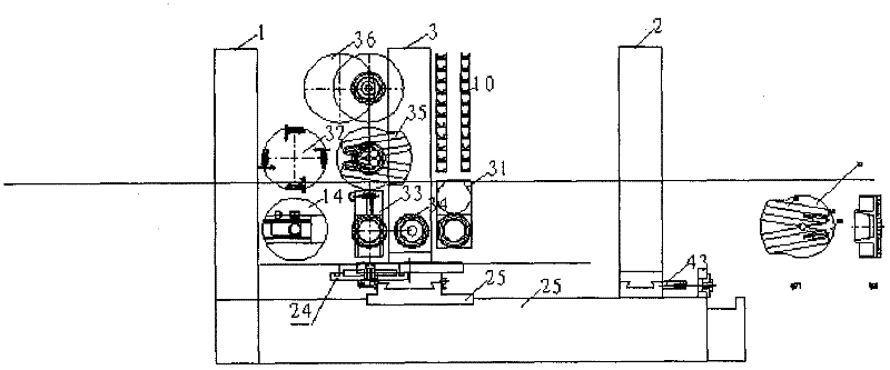
[0021] The machine tool of the present invention selects self-adaptive numerical control boring machine for use, comprises lathe bed 25, column 1, tailstock 2, knife rest 3, and column 1, tailstock 2 are fixedly installed on the bed, and bed is provided with workbench 22, and workbench 22 is connected with knife The frame 3 is connected by a rotary guide rail, the tool rest 3 is arranged on the workbench 22, and the spindle box 4 is arranged on the column 1, the tailstock 2 and the tool rest 3, the spindle box 4 is cylindrical, and the spindle box 4 is provided with Doubling group, also can not establish, directly drive with high-power servo motor. Multiplication group includes: multiplication group box body 44, is provided with servo motor 42 on the multiplication group box body 44, is provided with at least two groups of dual gears 45 in the multiplication group box body 44, a gear 46 in the dual gears and the first gear 48 meshing, the transmission ratio is 1: 1, another ge...
Embodiment 2
[0032] When the machine tool of the present invention is used as a milling machine, the structure and adjustment method of the present invention are the same as those in Embodiment 1. After the adjustment, the cutters of the column spindle 7 or the universal milling head 31 of the machine tool can be replaced with milling cutters. Horizontal, vertical and angular milling is possible.
[0033] Working process of milling machine:
[0034] The milling cutter is installed on the main shaft 7, and the workpiece adopts the three-degree-of-freedom movement mode in the embodiment 1 on the workbench 22, which can be used as a common milling machine for milling.
Embodiment 3
[0036] Lathe of the present invention is as sawing machine: when sawing box body, board parts, structure of the present invention and adjustment mode are identical with embodiment 1, after adjusting, this lathe changes the cutter 10 on column 1 main shaft 7 into saw blade. During as saw shaft class parts, the cutting tool on the knife rest 3 of invention lathe is replaced with saw blade, and flat rotating disc 14 is replaced with chuck 32.
[0037] work process:
[0038] For boring machines, when the main shaft 7 is replaced with a saw blade by the above tool change process, the workbench 22 is fed laterally, and this lathe becomes an ordinary numerical control plane sawing machine. Plane cutting is possible.
[0039] For lathes, after the lathe is processed, the knife rest 2 turns 180°, the workbench 22 moves to the saw blade position, and the saw blade is replaced, and the knife rest 2 returns. That is, it is adjusted to an ordinary CNC sawing machine, which can be cut off...
PUM
 Abstract
Description
Claims
Application Information
 - R&D
- Intellectual Property
- Life Sciences
- Materials
- Tech Scout
- Unparalleled Data Quality
- Higher Quality Content
- 60% Fewer Hallucinations
Browse by: Latest US Patents, China's latest patents, Technical Efficacy Thesaurus, Application Domain, Technology Topic, Popular Technical Reports.
© 2025 PatSnap. All rights reserved.Legal|Privacy policy|Modern Slavery Act Transparency Statement|Sitemap|About US| Contact US: help@patsnap.com