Distributed optical fiber sensor

A distributed optical fiber and sensor technology, applied in the direction of converting sensor output, using optical devices to transmit sensing components, optical instrument testing, etc., can solve the problem of not being able to separate and measure strain and temperature at the same time

Active Publication Date: 2011-10-26
NEUBREX
View PDF1 Cites 43 Cited by
  • Summary
  • Abstract
  • Description
  • Claims
  • Application Information

AI Technical Summary

Problems solved by technology

[0011] However, since the Brillouin frequency shift measured by the Brillouin scattering phenomenon changes depending on the two parameters of the optical fiber strain and temperature, the parameters that can be measured by the Brillouin scattering phenomenon are basically only the strain and temperature. One of them, strain and temperature cannot be separated and measured simultaneously

Method used


Image

  • Distributed optical fiber sensor
  • Distributed optical fiber sensor
  • Distributed optical fiber sensor

Examples


Embodiment Construction

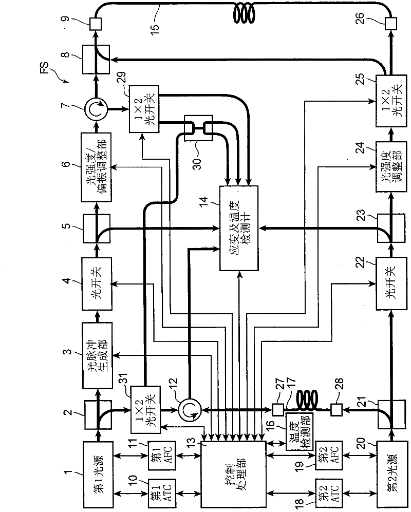
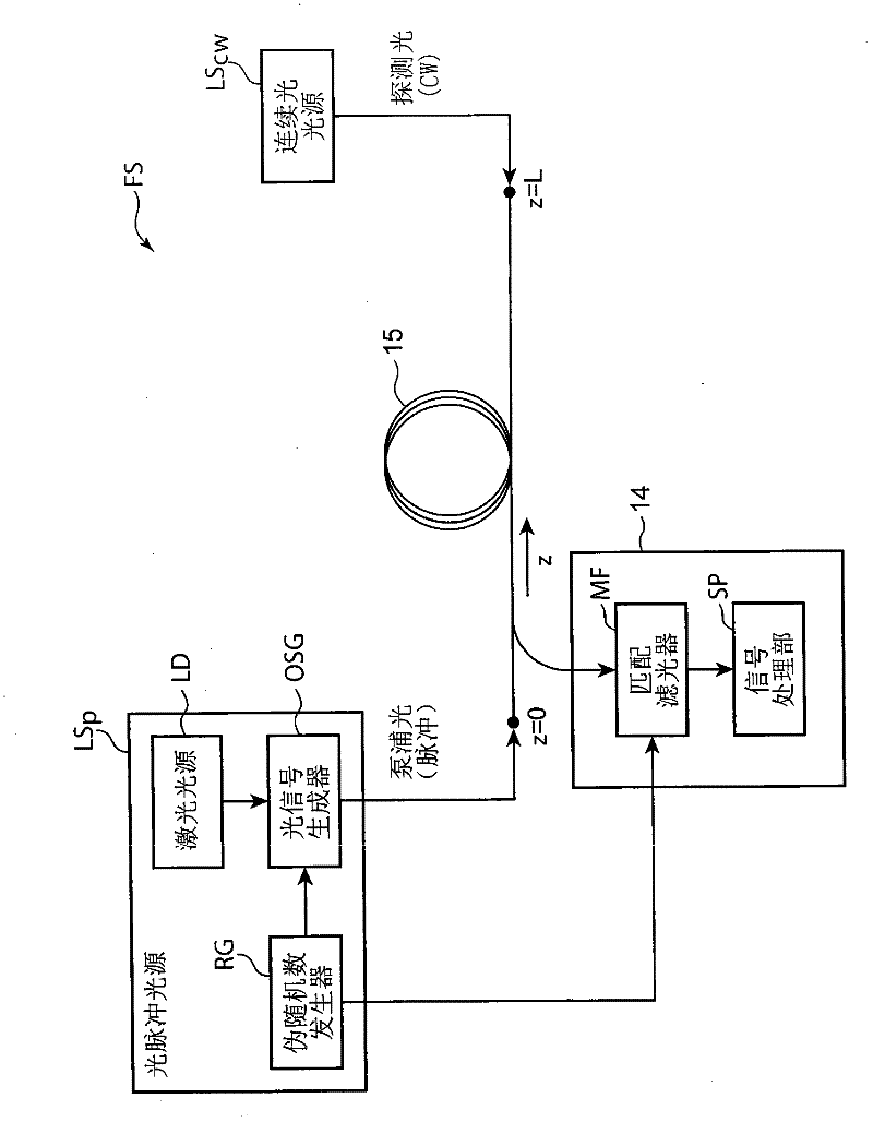
[0046] Hereinafter, a first embodiment of the distributed optical fiber sensor according to the present invention will be described based on the drawings. In addition, the structures to which the same code|symbol is attached|subjected in each drawing represent the same structure, and the description is abbreviate|omitted. figure 1 It is a block diagram showing the structure of the distributed optical fiber sensor in the first embodiment.

[0047] figure 1 The distributed optical fiber sensor FS shown includes a first light source 1, optical couplers 2, 5, 8, 21, 23, 30, an optical pulse generation unit 3, an optical switch 4, 22, an optical intensity / polarization adjustment unit 6, an optical Circulators 7, 12, optical connectors 9, 26, 27, 28, a first automatic temperature control unit (hereinafter, abbreviated as “first ATC”) 10, a first automatic frequency control unit (hereinafter, abbreviated as “first AFC”) ) 11, control processing unit 13, strain and temperature detec...


PUM


Abstract

Provided is a distributed optical fiber sensor capable of measuring the strain and temperature of an object to be measured simultaneously and independently with high spatial resolution. A distributed optical fiber sensor (FS) uses an optical fiber (15) as a sensor, wherein a distortion and temperature detector (14) measures the amount of Brillouin frequency shift due to the strain and temperature generated in the optical fiber (15) using a Brillouin scattering phenomenon, measures the amount of Rayleigh frequency shift due to the strain and temperature generated in the optical fiber (15) using a Rayleigh scattering phenomenon, and calculates the strain and temperature generated in the optical fiber (15) from the measured amount of Brillouin frequency shift and amount of Rayleigh frequency shift.

Description

technical field [0001] The invention relates to a distributed optical fiber sensor which uses optical fiber as a sensor and can measure strain and temperature with high precision in its length direction. Background technique [0002] Conventionally, as a technique for measuring strain and temperature, there is a method based on a Brillouin scattering phenomenon (Brillouin scattering phenomenon) caused in an optical fiber. In this method, an optical fiber is used as a medium for detecting strain and / or temperature in an environment (object to be measured) in which the optical fiber is installed. [0003] The so-called Brillouin scattering phenomenon refers to the phenomenon that energy moves through the acoustic phonon (acoustic phonon) in the optical fiber when light is injected into the optical fiber. The induced Brillouin scattering phenomenon caused by the interaction, and the natural Brillouin scattering phenomenon caused by the interaction of light entering the fiber a...

Claims


Application Information

Patent Timeline
Patent Type & Authority Applications(China)
IPC IPC(8): G01D5/353G01B11/16G01K11/12
CPCG01B11/18G01K11/32G01M11/083G01D5/35364G01L1/242G01K11/322G01B11/168G01N21/21
Inventor 李哲贤岸田欣增西口宪一阿鲁兹鲁·古兹库牧田笃山内良昭
Owner NEUBREX
Why Eureka
Try Eureka