
Impact-type high-temperature hardness test method

A hardness testing and impact technology, applied in the direction of testing the hardness of materials, etc., can solve the problems of low temperature upper limit and large test error, and achieve the effect of improving measurement accuracy, improving test accuracy and preventing temperature rise.

Inactive Publication Date: 2011-10-26
HARBIN INST OF TECH
View PDF4 Cites 8 Cited by
  • Summary
  • Abstract
  • Description
  • Claims
  • Application Information

AI Technical Summary

Problems solved by technology

[0005] The invention simultaneously solves the problems of low temperature upper limit and large test error in the current high-temperature hardness test method

Method used


Image

  • Impact-type high-temperature hardness test method
  • Impact-type high-temperature hardness test method

Examples


specific Embodiment approach 1

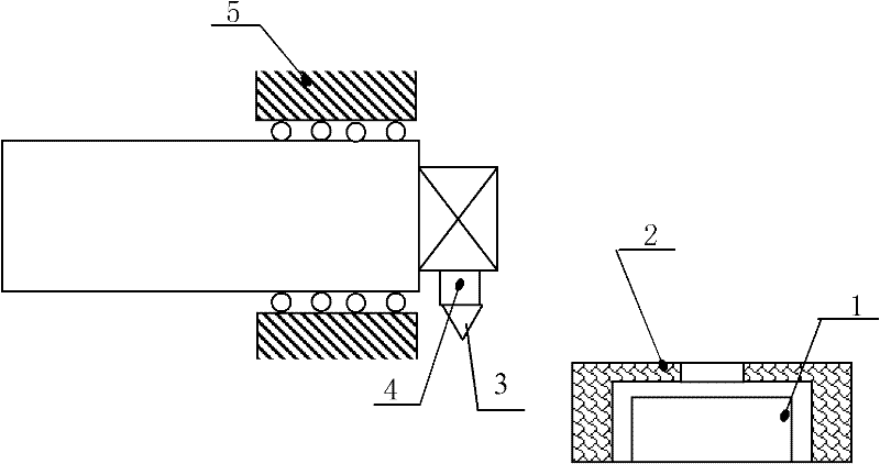
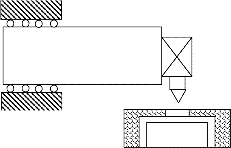
[0014] Specific implementation mode one: as Figure 1~2 As shown, an impact-type high-temperature hardness testing method described in this embodiment is based on a high-temperature hardness testing system including a vacuum device, a heating part, a probe moving mechanism, a water cooling system, and a hardness testing part. achieved;

[0015] The specific process of this high temperature hardness test method is:

[0016] Step 1. Place the sample 1 in the heater 2 with heat insulation function in the heating part, and maintain the vacuum degree in the heater 2 with heat insulation function by a vacuum device to be better than 2×10 -1 Pa; the sample 1 in it is heated to the set test temperature by the heater 2 with heat insulation function;

[0017] Step 2. Cool the outer surface of the vacuum device, the moving mechanism of the measuring head, the hardness testing part and the heater 2 with heat insulation function through the water cooling system, so that the hardness test...

specific Embodiment approach 2

[0022] Specific implementation mode two: as Figure 1~2 As shown, in the third step of this embodiment, after the second impact on the sample 1, a pulse current with an appropriate width twice the rated value is applied to the electromagnet of the electromagnetic mechanism, and the indenter bounced up for the second time Suction on the measuring head clamping mechanism 4; other steps are the same as in the first embodiment.

specific Embodiment approach 3

[0023] Specific implementation mode three: as Figure 1~2 As shown, this embodiment also adds the following steps: when the indenter that pops up for the second time is sucked on the probe clamping mechanism 4, the probe clamping mechanism 4 and the probe 3 are immediately translated by the probe moving mechanism 5 Return to the preparation area away from the insulated heater 2. Other steps are the same as in the second embodiment.


PUM

PropertyMeasurementUnit
temperatureaaaaaaaaaa

Abstract

An impact-type high-temperature hardness test method belongs to the technical field of hardness tests. The invention can solve the problems of low test precision and insufficient upper limit of test temperatures commonly seen in current hardness tests. In a current high-temperature hardness test, the temperature of a pressure head is the same as the test ambient temperature; elastic deformation or even plastic deformation of the pressure head can result in a bigger test error, which is also a main reason why the upper limit of the test temperature is limited at a lower level. The high-temperature hardness test method particularly comprises the following procedures: heating a sample to a set test temperature; allowing the part for hardness test to be in low-temperature environment through a water cooling system; when the sample reaches the set test temperature, rapidly moving a test head into the high-temperature region where the sample is located, realizing the free-falling control of the test head by an electromagnetic mechanism of the part for hardness test; allowing the pressure head to impact the upper surface of the sample in a free-falling manner and to fall again after rebound, determining the time interval between two impacts so as to obtain the high-temperature hardness value of the sample to be tested. The invention has an upper temperature limit of up to 1600 DEG C, and a test error of less than 2%.

Description

technical field [0001] The invention belongs to the technical field of hardness testing. Background technique [0002] The detection methods adopted by various standard hardness testers are limited to the detection at room temperature. However, in the related field of hardness testing, more and more attention is being paid to the law that the hardness of materials changes gradually with the increase of temperature. Using high-temperature hardness to indirectly characterize the high-temperature mechanical properties of materials has the advantages of low detection cost and high efficiency, and is an analytical method that is urgently needed by relevant research institutions. [0003] At present, the testing methods used in research papers that use the high-temperature hardness of materials to evaluate and characterize the high-temperature mechanical properties of materials are limited to Vickers hardness testing, and the upper limit temperature has only reached 1200 °C. Sin...

Claims


Application Information

Patent Timeline
Patent Type & Authority Applications(China)
IPC IPC(8): G01N3/52
Inventor 孙跃赫晓东宋广平
Owner HARBIN INST OF TECH
Learn More