High-power simplified electrolytic and electroplating high-frequency switch power supply and control method thereof

A high-frequency switching power supply, electrolytic electroplating technology, used in control/regulation systems, output power conversion devices, DC power input conversion to DC power output, etc. The total investment cost increases and other problems, to achieve the effect of suppressing current disturbance, realizing efficient utilization, reducing cost and loss

Active Publication Date: 2012-12-19
HUNAN UNIV
View PDF0 Cites 3 Cited by
  • Summary
  • Abstract
  • Description
  • Claims
  • Application Information

AI Technical Summary

Problems solved by technology

The traditional thyristor or diode rectifier circuit is very large and bulky. If Gordon switching power supply technology is adopted, its volume and weight will be greatly reduced, and it can greatly improve power utilization efficiency, save materials, reduce costs, and achieve high-efficiency power consumption and Combination of high-quality electricity
[0003] For large-scale electrolytic electroplating power supplies, the traditional electroplating electrolytic DC power supply adopts the thyristor phase-controlled rectification mode, so when the conduction angle of the thyristor is small, the power factor is low, and the harmonic content to the power grid is large, which directly leads to the installation of power transformers, connecting wires, switches, etc. The capacity increases, and generally large-capacity silicon controlled rectifiers also need to add additional harmonic control and power factor compensation devices, which greatly increases the total investment cost of users

Method used


Image

  • High-power simplified electrolytic and electroplating high-frequency switch power supply and control method thereof
  • High-power simplified electrolytic and electroplating high-frequency switch power supply and control method thereof
  • High-power simplified electrolytic and electroplating high-frequency switch power supply and control method thereof

Examples


Embodiment Construction

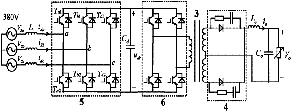
[0035] see figure 1 , which is a general high-power electrolytic plating high-frequency switching power supply structure diagram. It includes a three-phase rectifier 5, a single-phase full-bridge inverter 6, a high-frequency coupling transformer 3 and a low-voltage full-wave rectifier 4. The three-phase rectifier 5 is composed of three switching arms, that is, six power switches. Its AC input side is connected to the grid through a three-phase inductor L, and its DC side is connected to the grid through a capacitor C d Connect the next level circuit. In the figure, a single-phase full-bridge inverter 5, a high-frequency coupling transformer 3 and a low-voltage full-wave rectifier 4 constitute a high-frequency DC / DC converter. Wherein, the single-phase full-bridge inverter 6 is composed of 2 switching arms, that is, 4 power switches.

[0036] After the three-phase alternating current is rectified by the three-phase rectifier PWM, a constant direct current is obtained. Then,...


PUM


Abstract

The invention discloses a high-power simplified electrolytic and electroplating high-frequency switch power supply and a control method thereof. The simplified electrolytic and electroplating high-frequency switch power supply comprises a three-phase inverter based on three phases and two arms, and a high-frequency DC / DC converter that is formed by serially connecting a single-phase half-bridge inverter, a high-frequency coupling transformer and a low-voltage full-wave rectifier; the three-phase inverter based on the three phases and two arms is formed by connecting two switch arms and two serially-connected capacitor branches at the direct-current side in parallel; the single-phase half-bridge inverter is formed by connecting a switch arm and two serially-connected capacitor branches at the direct-current side in parallel; the three-phase inverter and the single-phase half-bridge inverter commonly share one group of direct-current side capacitors; the input terminal of the three-phase inverter is connected with a power network by a three-phase inductor L; and the output terminal of the three-phase inverter is connected with the single-phase half-bridge inverter. The switch power supply has few switch devices, small loss, high efficiency, small direct-current ripples, high response speed and small voltage distortion and current distortion. The method in the invention has the advantages of improving the response speed of the three-phase inverter and tracking the change of the load power in real time.

Description

technical field [0001] The invention relates to a switching power supply and a control method thereof, in particular to a high-power simplified electrolytic plating high-frequency switching power supply and a comprehensive control method thereof. Background technique [0002] In the application of power electronics technology and various power supply systems, switching power supply technology is at the core. In the electric vehicle, frequency conversion drive and electrolytic plating industry, switching power supply technology is even more inseparable. Through switching power supply, the frequency of power consumption can be changed, so as to achieve near-ideal load matching and drive control. The traditional thyristor or diode rectifier circuit is very large and bulky. If Gordon switching power supply technology is adopted, its volume and weight will be greatly reduced, and it can greatly improve power utilization efficiency, save materials, reduce costs, and achieve high-e...

Claims


Application Information

Patent Timeline
Patent Type & Authority Patents(China)
IPC IPC(8): H02M7/12H02M7/219H02M3/335
Inventor 罗安马伏军谢宁张寅王刚王晓刘芸
Owner HUNAN UNIV
Why Eureka
Try Eureka