


Quick Research
Generate reliable direction feasibility study reports for your R&D in just a few steps.

Technical Q&A
Discover and master advanced knowledge NOW. Basics, ideas, possibilities, all at once.

Find Solutions
As an expert in R&D theories, this can generate solutions to your technical problems instantly.

Evaluate Feasibility
Analyze your overall solution with one click, know your potential R&D risks in advance.

Monitor Landscape
Get weekly tech updates, stay abreast of the latest tech innovations and key insights.
Valve
A technology of valve holes and valve pistons, applied in valve details, multi-way valves, valve devices, etc., can solve problems such as device technical expenses and achieve the effect of cost reduction
- Summary
- Abstract
- Description
- Claims
- Application Information
AI Technical Summary
Problems solved by technology
Method used
Image

Examples
Embodiment Construction
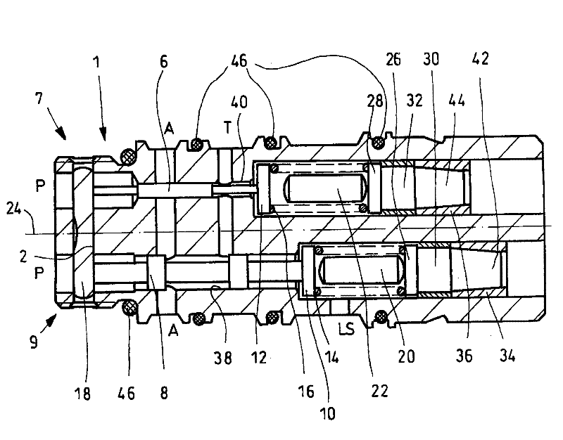
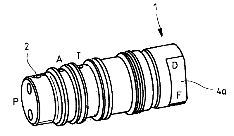
[0028] figure 1 A perspective view of a first exemplary embodiment with a combined valve arrangement consisting of two valves according to the invention is shown. The valve device is a pressure delivery flow regulator whose housing is designed as a cartridge valve 1 . This cartridge valve 1 can be screwed into a control pump (not shown) to save installation space.
[0029] A control pressure connection A and a tank connection T are arranged on the outer circumference of the cartridge valve 1 , while a control pressure connection P is arranged on the end face. This control pressure connection P is used for “reporting” the pump pressure of the regulating pump, wherein a bore of the control pressure connection P is assigned to each of the two valves. The control pressure connection A is used to adjust the swivel angle of the regulating pump via a (not shown) adjusting cylinder, and the tank connection T is connected to a tank (not shown).
[0030] Adjacent to the control press...
PUM
 Abstract
Description
Claims
Application Information
 - R&D Engineer
- R&D Manager
- IP Professional
- Industry Leading Data Capabilities
- Powerful AI technology
- Patent DNA Extraction
Browse by: Latest US Patents, China's latest patents, Technical Efficacy Thesaurus, Application Domain, Technology Topic, Popular Technical Reports.
© 2024 PatSnap. All rights reserved.Legal|Privacy policy|Modern Slavery Act Transparency Statement|Sitemap|About US| Contact US: help@patsnap.com