Power source
A technology of power supply device and electrode group, which is applied in the direction of circuits, electric vehicles, electrical components, etc., can solve the problems of single battery performance degradation, heat difficulty, heat transfer, etc., and achieve the effect of suppressing temperature rise
- Summary
- Abstract
- Description
- Claims
- Application Information
AI Technical Summary
Problems solved by technology
Method used
Image
Examples
Embodiment approach 1
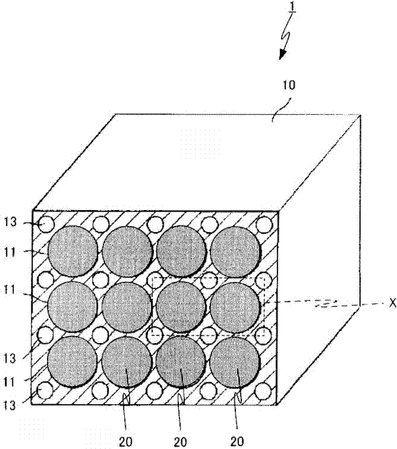
[0128] Figure 4 It is a perspective view of the power supply device 100 according to the first embodiment. Figure 5 It is a front view of the power supply device 100 of Embodiment 1. .
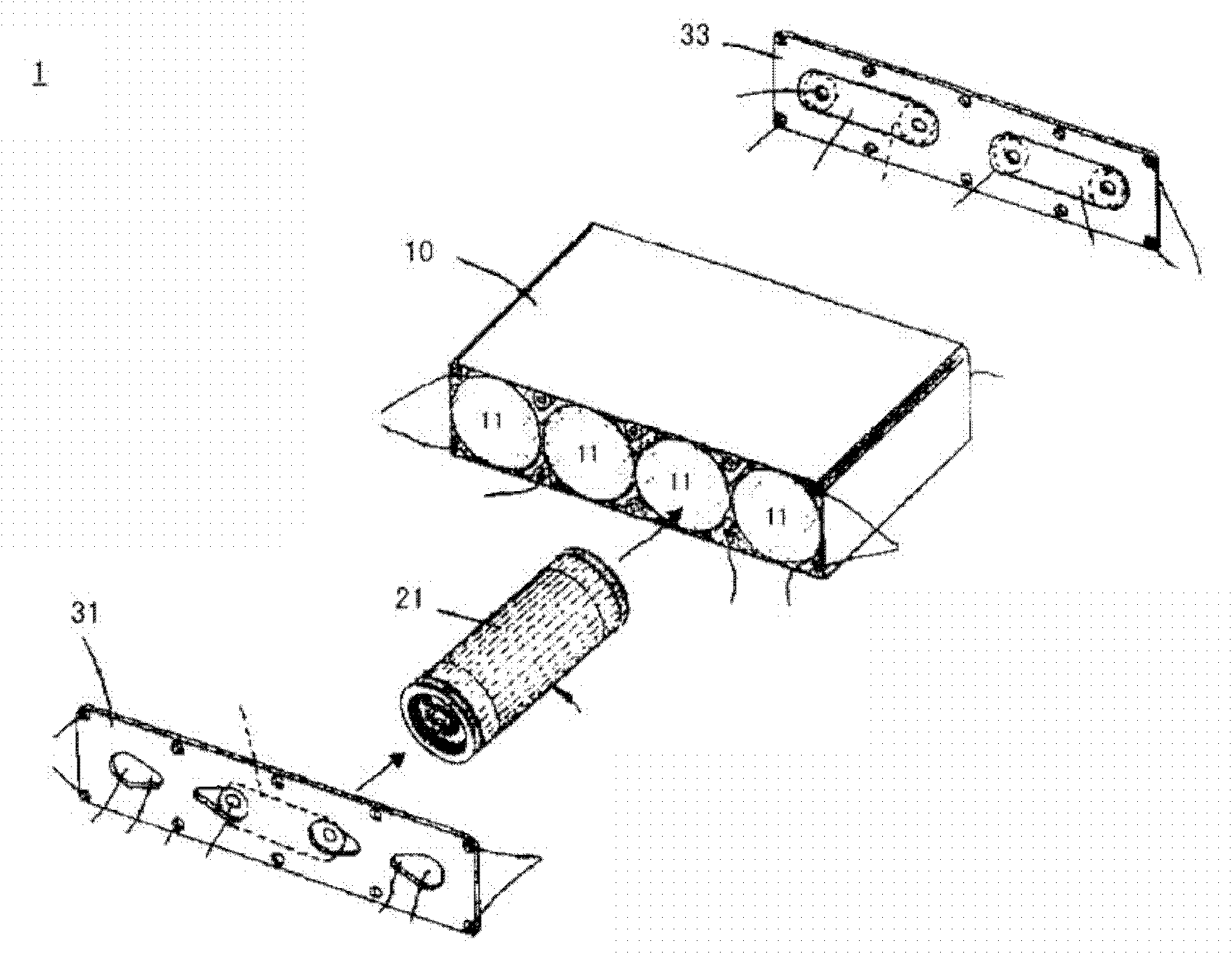
[0129] Such as Figure 4 and 5 As shown, the power supply device 100 has a molded body 110 and a unit 120 . Furthermore, the power supply device 100 has a positive electrode sealing plate 130 and a negative electrode sealing plate 140 (refer to Figure 10 ).
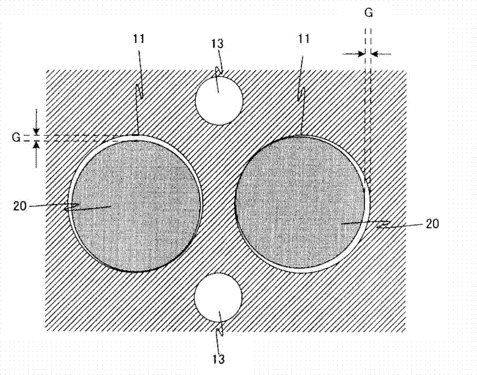
[0130] The molded body 110 is, for example, a conductive member made of aluminum. The molded body 110 has a plurality of receiving holes 111 . The receiving hole 111 penetrates the molded body 110 . The storage hole 111 accommodates the unit 120 .
[0131] The size of the molded body 110 is not particularly limited, for example, the length L is 140 to 180 mm, the width W is 50 to 90 mm, and the height H is 40 to 80 mm (refer to Figure 4 ). In addition, the diameter Φ of the storage hole is 10 to 30 mm (refer to Figure 5 )...
Embodiment approach 2
[0155] In Embodiment 1, a mode in which each positive electrode sealing plate is independent is described. In Embodiment 2, the mode in which the power supply device has one positive electrode sealing plate that seals all the storage holes will be described.
[0156] Figure 13 It is an exploded perspective view of the power supply device 200 according to the second embodiment. The power supply unit 200 is connected to the positive electrode sealing plate, and Figure 4 The power supply device 100 of Embodiment 1 shown is the same. The same reference numerals are assigned to the same components as those of the power supply device 100 according to Embodiment 1, and description thereof will be omitted.
[0157] Such as Figure 13 As shown, the power supply device 200 has a positive sealing plate 240 . In this way, in the present embodiment, since the positive electrode sealing plate 240 is not individually divided for each cell 120 , the number of components is small, and t...
Embodiment approach 3
[0159] In Embodiment 1 and Embodiment 2, the embodiment in which the storage hole penetrates the molded body has been described. In Embodiment 3, the mode in which the storage hole does not penetrate the molded body will be described.
[0160] Figure 14 It is a sectional view of the power supply device 300 according to the third embodiment. The power supply device 300 is different from the shape of the receiving hole 211 except that Figure 10 The power supply device 100 of Embodiment 1 shown is the same. The same reference numerals are assigned to the same components as those of the power supply device 100 according to Embodiment 1, and description thereof will be omitted.
[0161] Such as Figure 14 As shown, the power supply device 300 has a molded body 210 and a sealing plate 230 . The molded body 210 has a storage hole 211 . The receiving hole 211 does not penetrate the molded body 210 . Such a molded body 210 can be molded by press molding, for example.
[0162]...
PUM
| Property | Measurement | Unit |
|---|---|---|
| particle diameter | aaaaa | aaaaa |
| heat capacity | aaaaa | aaaaa |
| heat capacity | aaaaa | aaaaa |
Abstract
Description
Claims
Application Information
 - R&D Engineer
- R&D Manager
- IP Professional
- Industry Leading Data Capabilities
- Powerful AI technology
- Patent DNA Extraction
Browse by: Latest US Patents, China's latest patents, Technical Efficacy Thesaurus, Application Domain, Technology Topic, Popular Technical Reports.
© 2024 PatSnap. All rights reserved.Legal|Privacy policy|Modern Slavery Act Transparency Statement|Sitemap|About US| Contact US: help@patsnap.com


