Closed gas cycle type thermal power system
A thermodynamic, gas-closed technology, which can be used in charging systems, exhaust devices, engine components, etc., and can solve problems such as difficulty in carbon dioxide treatment
- Summary
- Abstract
- Description
- Claims
- Application Information
AI Technical Summary
Problems solved by technology
Method used
Image
Examples
Embodiment 1
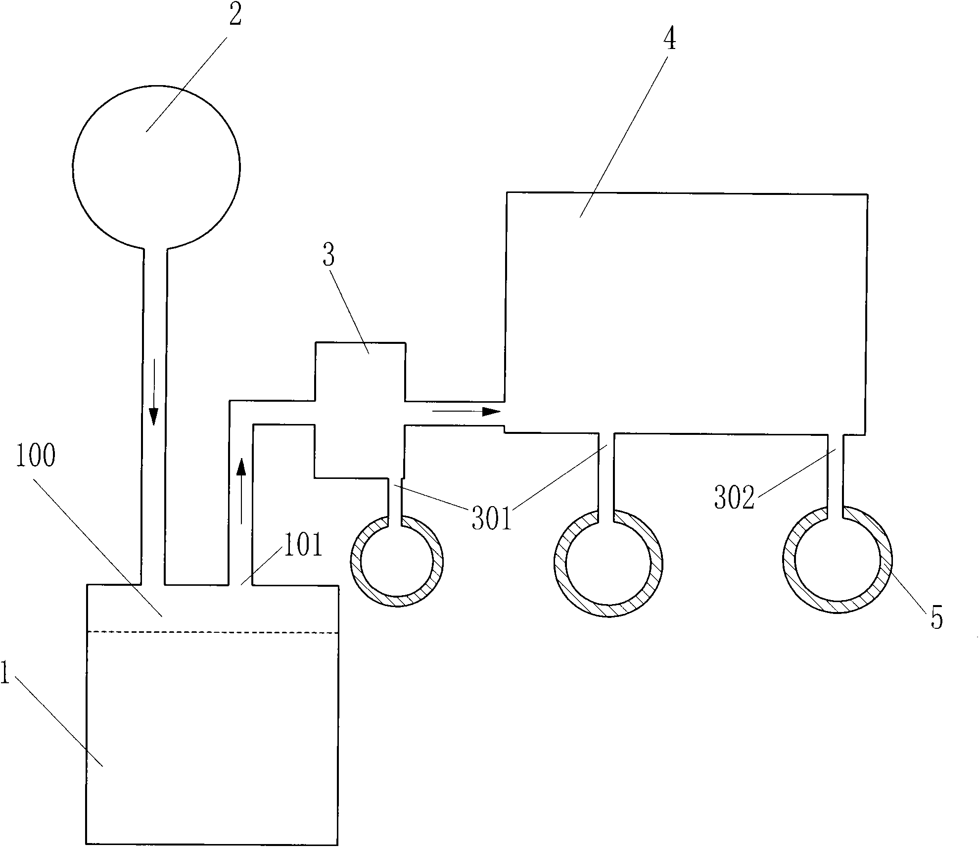
[0098] Such as figure 1 The gas closed-cycle thermodynamic system shown includes an engine 1, an oxygen source 2, an exhaust cooler 3, an exhaust deep cooler 4, and a cryogenic carbon dioxide storage tank 5. The oxygen source 2 communicates with the combustion chamber 100 of the engine 1, The exhaust duct 101 of the engine 1 communicates with the exhaust deep cooler 4 through the exhaust cooler 3, a water discharge port 301 is set on the exhaust cooler 3, and a cryogenic carbon dioxide discharge port 302 is set on the exhaust deep cooler 4 The cryogenic carbon dioxide outlet 302 communicates with the cryogenic carbon dioxide storage tank 5 so that all or part of the carbon dioxide in the exhaust gas of the engine 1 is stored in the cryogenic carbon dioxide storage tank 5 in the form of liquid and / or solid.
Embodiment 2
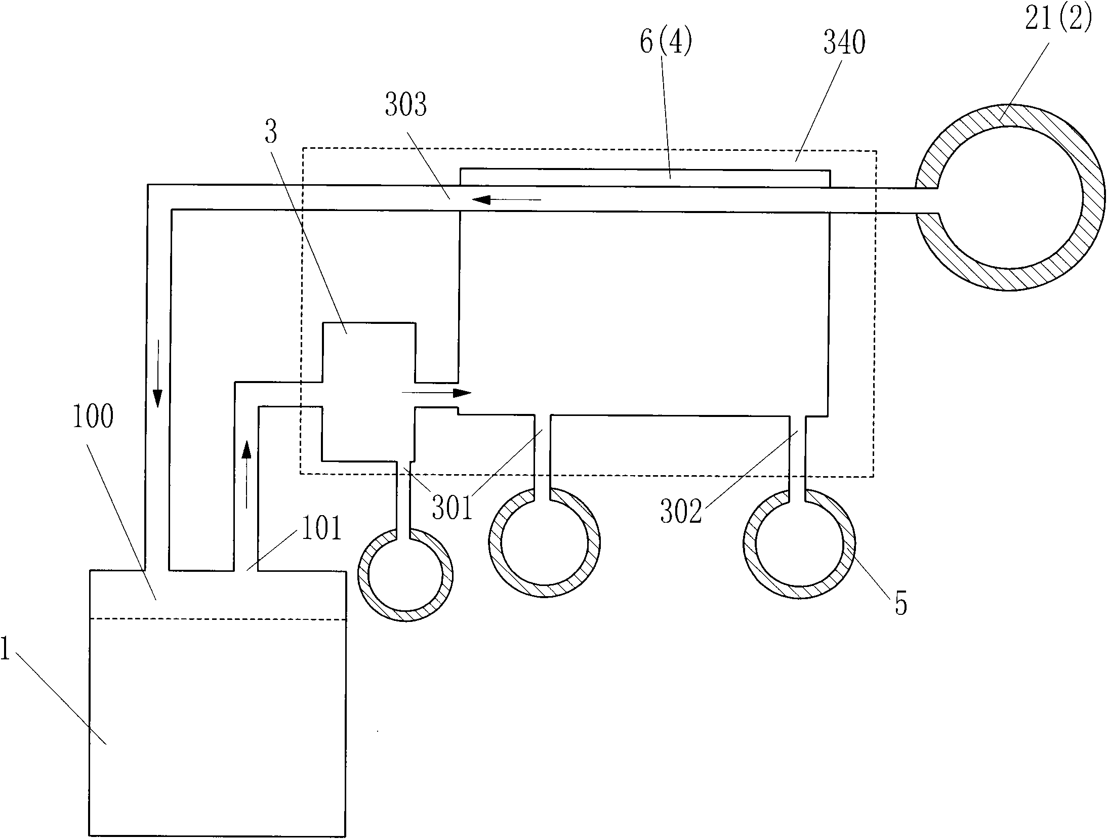
[0100] Such as figure 2 The gas closed cycle thermodynamic system shown differs from Embodiment 1 in that: the oxygen source 2 is set as a liquid oxygen storage tank 21, and the exhaust gas deep cooler 4 is set as an oxygen endothermic exhaust gas deep cooler 6. The endothermic exhaust deep cooler 6 is provided with a water outlet 301 and a cryogenic carbon dioxide outlet 302, and the liquid oxygen storage tank 21 communicates with the cooling fluid inlet of the oxygen endothermic exhaust deep cooler 6. An oxygen / oxygen-containing gas outlet 303 is provided on the cooler 6 , and the oxygen / oxygen-containing gas outlet 303 communicates with the combustion chamber 100 of the engine 1 . In addition, the exhaust gas cooling system 340 composed of the exhaust gas cooler 3 and the exhaust gas subcooler 4 can also be set as an oxygen endothermic exhaust gas subcooler, and the oxygen endothermic exhaust gas subcooler cools the exhaust gas to a depth Cooling liquefies the water vapor...
Embodiment 3
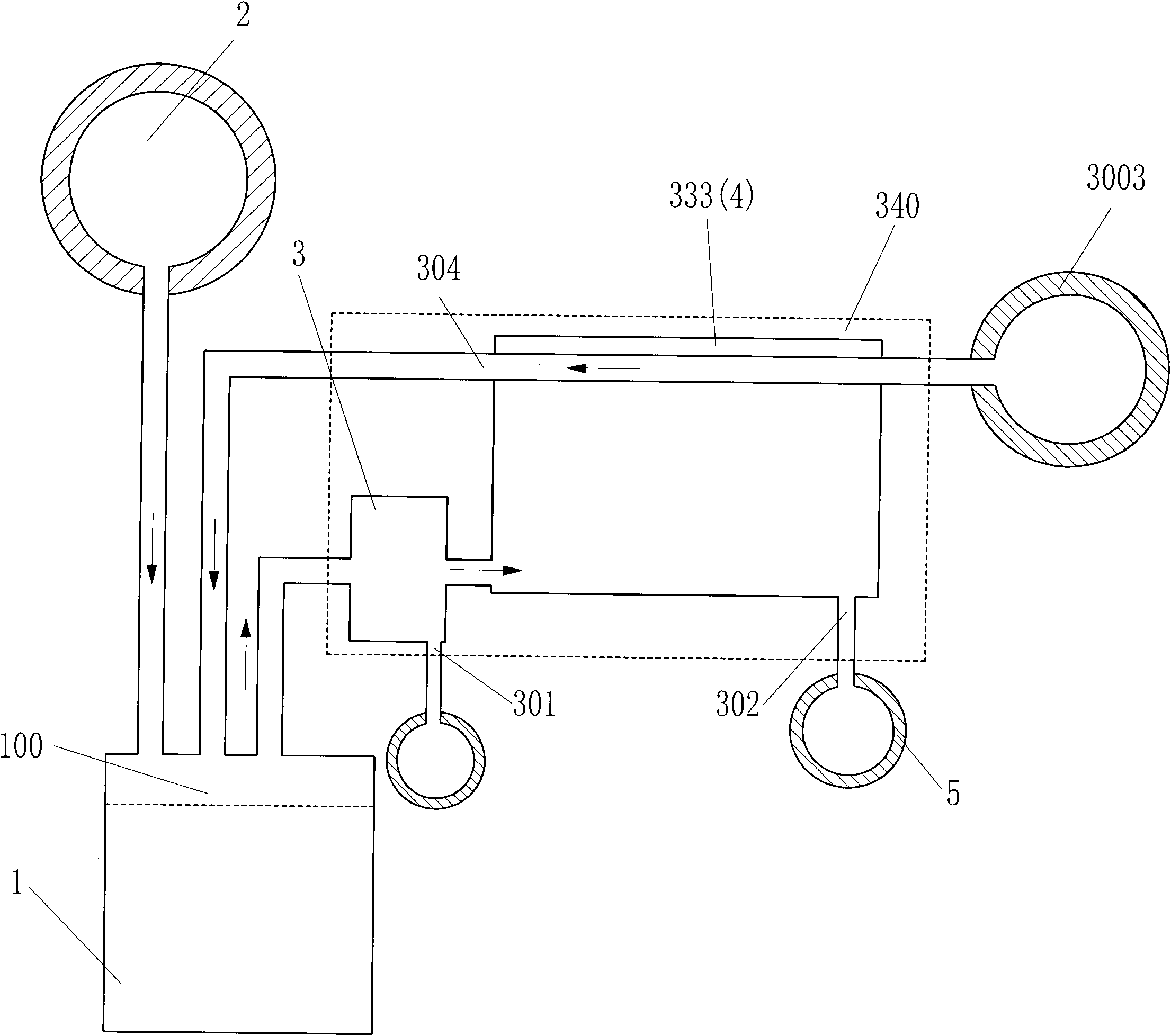
[0102] Such as image 3 The gas closed cycle thermal power system shown differs from Embodiment 1 in that: the fuel of the engine 1 is set as liquefied fuel, the liquefied fuel is stored in the liquefied fuel storage tank 3003, and the exhaust gas deep cooler 4 is set as the fuel absorbing heat The exhaust gas deep cooler 333 is provided with a cryogenic carbon dioxide outlet 302 on the fuel heat-absorbing exhaust gas deep cooler 333, and the cooling fluid inlet of the fuel heat-absorbing exhaust gas deep cooler 333 communicates with the liquefied fuel storage tank 3003. The hot exhaust subcooler 333 is provided with a fuel / fuel-containing fluid outlet 304 , and the fuel / fuel-containing fluid outlet 304 communicates with the combustion chamber 100 of the engine 1 . In addition, the exhaust gas cooling system 340 composed of the exhaust gas cooler 3 and the exhaust gas deep cooler 4 can also be used as a fuel heat-absorbing exhaust gas deep cooler, and the fuel heat-absorbing e...
PUM
 Abstract
Description
Claims
Application Information
 - R&D Engineer
- R&D Manager
- IP Professional
- Industry Leading Data Capabilities
- Powerful AI technology
- Patent DNA Extraction
Browse by: Latest US Patents, China's latest patents, Technical Efficacy Thesaurus, Application Domain, Technology Topic, Popular Technical Reports.
© 2024 PatSnap. All rights reserved.Legal|Privacy policy|Modern Slavery Act Transparency Statement|Sitemap|About US| Contact US: help@patsnap.com


