Vehicle brake mechanism and method for controlling the vehicle brake mechanism

The technology of a braking device and a control method, which is applied in the direction of a braking transmission device, a braking action starting device, a brake, etc., can solve problems such as loss of braking force of a wheel cylinder, complicated structure of a slave cylinder, etc., and achieve the effect of structural simplification

Inactive Publication Date: 2011-10-12
HONDA MOTOR CO LTD
View PDF10 Cites 18 Cited by
  • Summary
  • Abstract
  • Description
  • Claims
  • Application Information

AI Technical Summary

Problems solved by technology

[0004] However, in the above-mentioned conventional device, the slave cylinder needs to have the first and second hydraulic chambers corresponding to the wheel cylinders of the first system and the wheel cylinder of the second system, so there is a problem that the structure of the slave cylinder is complicated.
In order to solve this problem, when the brake hydraulic pressure is supplied from the slave cylinder with a single hydraulic chamber to the wheel cylinders of the first and second systems, the brake hydraulic pressure generated by the master cylinder will operate the wheel cylinders when the slave cylinder fails. If there is a defect such as fluid leakage in the wheel cylinder of one of the first and second systems, there is a possibility that the braking force of the wheel cylinders of both the first and second systems will be lost.

Method used


Image

  • Vehicle brake mechanism and method for controlling the vehicle brake mechanism
  • Vehicle brake mechanism and method for controlling the vehicle brake mechanism
  • Vehicle brake mechanism and method for controlling the vehicle brake mechanism

Examples


Embodiment Construction

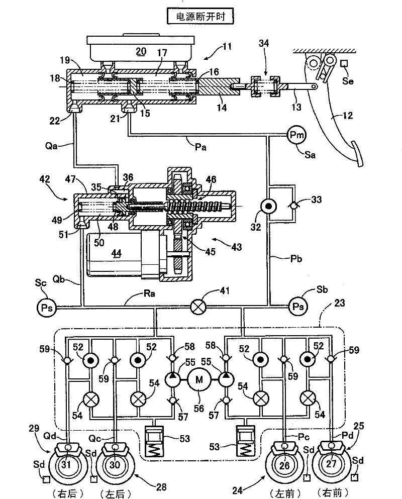
[0049] Below, based on Figure 1 to Figure 7 , to describe the embodiment of the present invention.

[0050] Such as figure 1 As shown, the tandem master cylinder 11 is equipped with a first piston 14 connected to the brake pedal operated by the driver via a push rod 13 and a second piston 15 arranged in front of it, and is divided into the first piston 14 and the second piston. A first hydraulic chamber 17 in which a return spring 16 is accommodated between the pistons 15 , and a second hydraulic chamber 19 in which a return spring 18 is accommodated in front of the second piston 15 . A stroke simulator 34 made of a spring is disposed at an intermediate position of the push rod 13 .

[0051] The first hydraulic chamber 17 and the second hydraulic chamber 19, which can communicate with the liquid storage chamber 20, respectively have a first output port 21 and a second output port 22. The first output port 21 is a normally open electromagnetic valve through the liquid path P...


PUM


Abstract

A vehicle brake mechanism and a method for controlling the vehicle brake mechanism. In a BBW brake mechanism, a driven cylinder having a single hydraulic with a simple structure is employed so as to realize the standby when one system in two brake systems is failed. A master cut valve 32 is closed and a connection control valve 41 is opened to make first and second liquid paths Pb, Qb connect with the driven cylinder 42, thereby simplifying the structure without a serial driven cylinder. When the power supply is failed, the master cut valve 32 is opened and the connection control valve 41 is closed. The brake hydraulic pressure generated by the first and second hydraulic chambers of the master cylinder 11 respectively drives the wheel cylinders 26, 27, 30, and 31 of the first and second systems to act. Herein, the brake force is guaranteed through the action of the other system even if one system in the first and second systems generates the liquid leakage defect because the first and second liquid paths Pb, Qb are separated.

Description

technical field [0001] The present invention relates to a so-called BBW (full circuit brake) system that converts the operation of the brake pedal by the driver into an electric signal, and uses the brake hydraulic pressure generated by the slave cylinder controlled based on the electric signal to activate the wheel cylinder. A braking device for a vehicle and a control method thereof. Background technique [0002] According to the following patent document 1, it is known that such a BBW-type vehicle brake device includes a tandem master cylinder, a tandem slave cylinder, a first system wheel cylinder, and a second system wheel cylinder, so that the master cylinder The first hydraulic chamber of the cylinder is connected with the wheel cylinder of the first system via the first hydraulic chamber of the slave cylinder, and the second hydraulic chamber of the master cylinder is connected with the wheel cylinder of the second system via the second hydraulic chamber of the slave...

Claims


Application Information

Patent Timeline
Patent Type & Authority Applications(China)
IPC IPC(8): B60T8/40B60T13/74
CPCB60T1/10B60T7/042B60T8/4081B60T13/161B60T13/745
Inventor 大久保直人井上亚良太西冈崇
Owner HONDA MOTOR CO LTD
Why Eureka
Try Eureka