
Method of running diaphragm pump, diaphragm pump and use of diaphragm pump

A diaphragm type, pipeline system technology, applied in the field of diaphragm type pump, can solve the problems of natural frequency change, inaccurate natural frequency, less effective pump effect, etc., to achieve the effect of increasing resonance

Inactive Publication Date: 2011-10-05
ROBERT BOSCH GMBH
View PDF5 Cites 3 Cited by
  • Summary
  • Abstract
  • Description
  • Claims
  • Application Information

AI Technical Summary

Problems solved by technology

[0007] The problem here, however, is that the natural frequency of the system often undergoes significant variations, so that the natural frequency cannot be determined exactly
In general the pumping effect of resonance is seldom effective because the natural frequency does not appear exactly

Method used


Image

  • Method of running diaphragm pump, diaphragm pump and use of diaphragm pump
  • Method of running diaphragm pump, diaphragm pump and use of diaphragm pump

Examples


Embodiment Construction

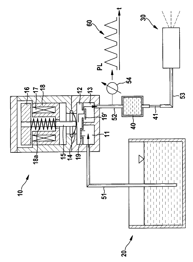
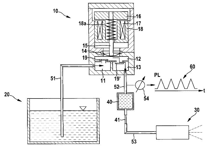
[0021] The drawing shows an electromagnetic diaphragm pump 10 used as a supply pump or metering pump for an SCR exhaust gas purification system. The diaphragm pump 10 conveys the water-soluble urea solution from the tank 20 to the metering device 30 . The dosing device 30 includes, for example, a solenoid injection valve, with which a water-soluble urea solution is injected as required into an exhaust line (not shown). The liquid medium is conveyed from the reducing agent tank 20 into the suction region 11 of the diaphragm pump 10 via the suction line 51 . The medium passes through the first non-return valve 19 into the diaphragm working chamber 12 and through the second non-return valve 19 ′ into the delivery region 13 of the diaphragm pump 10 . The liquid is delivered via the membrane 14 moved by the delivery piston 15 . The delivery piston 15 is connected to an armature 16 which is forced to move by means of a magnetic field generated by a ring coil 17 inside a lifting ma...


PUM


Abstract

The invention relates to a method of running a diaphragm pump, a diaphragm pump and the use of the diaphragm pump. The method of running the electromagnetic diaphragm pump (10) in pipeline systems (51,52,53) comprises a step of exciting the diaphragm pump (10) with a frequency corresponding to an inherent frequency. The method is characterized in that a stored liquid mass (40) is supplemented by the mass of the diaphragm pump (10) running on the downstream. The stored liquid mass can be separated from another pipeline system (53) through a lock (41) on the downstream of the stored liquid mass (40).

Description

technical field [0001] The invention relates to a method for operating an electromagnetic diaphragm pump, in which the diaphragm pump is excited with a frequency corresponding to the natural frequency. Furthermore, the invention relates to a diaphragm pump and the use of a diaphragm pump which are suitable for carrying out the method according to the invention. Background technique [0002] Methods and devices are known for operating an internal combustion engine, in particular in a motor vehicle in which an SCR catalytic converter ( S elective C analytic R reduction), which uses a reducing agent to reduce nitrogen oxides (NOx) contained in the exhaust gas of an internal combustion engine relative to nitrogen. As a result, the proportion of nitrogen oxides in the exhaust gas can be significantly reduced. Ammonia (NH 3 ). NH 3 or NH 3 The dissociated reagents are used as reactants. A water-soluble urea solution is usually used for this purpose, which is injected into...

Claims


Application Information

Patent Timeline
IPC IPC(8): F04B43/04
CPCF04B17/042F04B43/04F04B23/02
Inventor R·哈贝勒
Owner ROBERT BOSCH GMBH
Learn More