Soybean milk maker
A soymilk machine and machine body technology, which is applied in the field of soymilk machines with powdering function, can solve the problems of not being able to make powder without water, and can only make soymilk with water, so as to achieve the effect of reducing the powdering space, making the powdering fine, and ensuring the powdering effect
- Summary
- Abstract
- Description
- Claims
- Application Information
AI Technical Summary
Problems solved by technology
Method used
Image
Examples
specific Embodiment 1
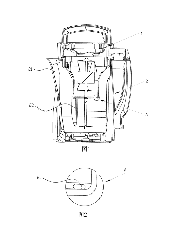
[0035] Such as figure 1 As shown, the soybean milk maker of the present invention includes a head 1, a body 2 and a control circuit, the head 1 is provided with a motor and a crushing knife arranged on the output shaft of the motor, and the body 2 is provided with a Heating element, rib 22 and nozzle 21. Of course, in the technical solution of the present invention, only the ribs 22 may be provided, or only the nozzle 21 may be provided.
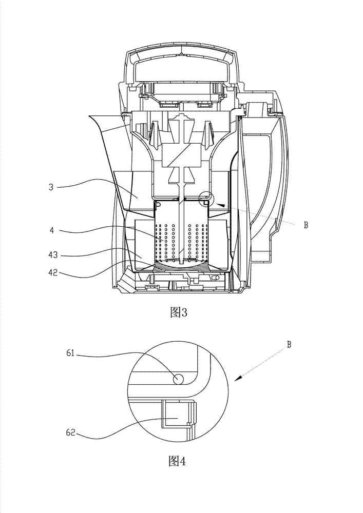
[0036] Such as image 3 As shown, the soymilk machine of the present invention is provided with a detachable powder making device, the powder making device includes a storage box 3 and a powder beating container 4 , and the powder beating container 4 is arranged below the powder storage 3 .
[0037] Such as Figure 5 As shown, the storage box 3 is provided with a groove 32 corresponding to the rib 22, and the groove 32 cooperates with the rib 22 to limit the storage box 3 in the fuselage 2. circular movement. Or the storage box 3 is pro...
specific Embodiment 2
[0049] The main difference between this embodiment and Embodiment 1 is that the elastic parts between the material storage box 3 and the powder beating container 4 are different, because the difference of the elastic parts makes the material storage box 3 and the powder beating container There are some differences in the structure related to the elastic member on the dish 4 . Such as Figure 9 As shown, the bottom edge of the storage box 3 protrudes a step 34 inwardly, as Figure 10 As shown, a flange 44 corresponding to the step 34 is provided on the peripheral wall of the powdering container 4, and the steps 34 and the flange 44 cooperate with each other so that the storage box 3 and the powdering container 4 are in the same position. The direction of the central axis will not be separated.
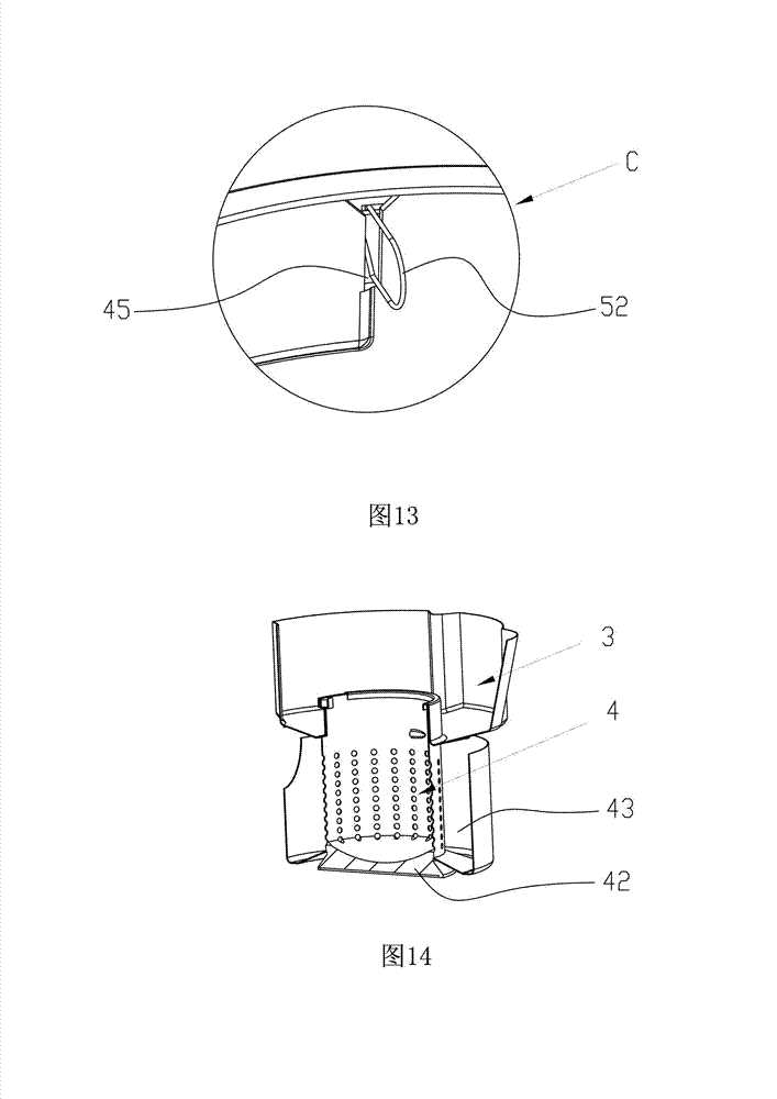
[0050] Such as Figure 9 As shown, the inner wall of the storage box 3 is provided with a tension spring 52, and the tension spring 52 is a structure of an elastic member arranged be...
specific Embodiment 3
[0052] The main difference between this embodiment and Embodiment 1 or Embodiment 2 is that: Figure 14 As shown, a heat transfer plate 42 is welded at the bottom of the powder-making dish 4 , and a powder-collecting box 43 is welded around the periphery of the powder-making dish 4 . The advantage of this setting is that the food materials can be roasted to make powdered food with different flavors. The powder dish 4 , the heat transfer plate 42 and the powder collection box 43 are integrally formed.
[0053] Preferably, the bottom surface of the powder collecting box 43 is inclined downward from inside to outside. The advantage of such setting is: while satisfying heat insulation between the powder collection box and the heat transfer plate 42 at 43 , it reduces the clogging of the pinhole 47 on the powder dish 4 by powder.
[0054] The main difference between the working principle and process of this embodiment and that of Embodiment 1 is: powering on the soybean milk mach...
PUM
 Abstract
Description
Claims
Application Information
 - Generate Ideas
- Intellectual Property
- Life Sciences
- Materials
- Tech Scout
- Unparalleled Data Quality
- Higher Quality Content
- 60% Fewer Hallucinations
Browse by: Latest US Patents, China's latest patents, Technical Efficacy Thesaurus, Application Domain, Technology Topic, Popular Technical Reports.
© 2025 PatSnap. All rights reserved.Legal|Privacy policy|Modern Slavery Act Transparency Statement|Sitemap|About US| Contact US: help@patsnap.com


