
Motor driving apparatus easily analyzable for cause of fault

A driving device and motor technology, applied in the direction of motor control, AC motor control, output power conversion device, etc., can solve the problem that there is no record of input power

Active Publication Date: 2011-09-28
FANUC LTD
View PDF7 Cites 20 Cited by
  • Summary
  • Abstract
  • Description
  • Claims
  • Application Information

AI Technical Summary

Problems solved by technology

But there is no record about the input power

Method used


Image

  • Motor driving apparatus easily analyzable for cause of fault
  • Motor driving apparatus easily analyzable for cause of fault
  • Motor driving apparatus easily analyzable for cause of fault

Examples


Embodiment Construction

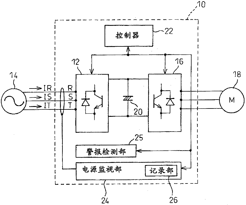
[0017] figure 1 It is a block diagram showing the configuration of the motor drive device 10 according to one embodiment of the present invention. Converter 12 converts three-phase AC from three-phase AC power supply 14 into DC. The inverter 16 converts the direct current from the converter 12 into a variable-frequency three-phase alternating current, and supplies it to the motor 18 . A smoothing capacitor 20 is provided between the converter 12 and the inverter 16 . Controller 22 controls converter 12 and inverter 16 .

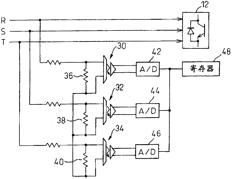
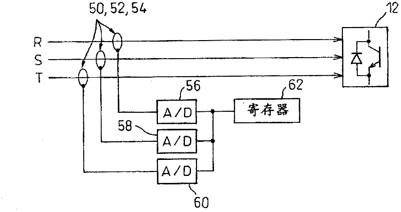
[0018] The power supply monitoring part 24 detects the voltage and current of each phase of the three-phase AC input to the converter 12, and monitors whether there are abnormalities such as power failure, phase loss, voltage imbalance, overvoltage, and overcurrent, and reports to the controller 22 if there is an abnormality. Send an alarm signal, and perform protective actions such as motor running and stopping. The power supply monitoring unit 24 also s...


PUM


Abstract

Disclosed is a motor driving apparatus in which provisions are made so as to easily isolate the cause of a fault in the event of the occurrence thereof. The voltage and current in each phase of the AC power being supplied to a converter are detected, and the most recently detected data are stored in a power supply monitoring unit for a predetermined period of time. If an alarm occurs in the converter, inverter, or controller, the data currently held in the power supply monitoring unit are recorded in a recording unit. By displaying the thus recorded data, one can easily identify whether the cause of the alarm is due to the power supply or the motor driving apparatus itself.

Description

technical field [0001] The present invention relates to a motor drive device capable of easily distinguishing whether the cause is an input power supply or the device itself when an abnormality occurs. Background technique [0002] In motor control devices that drive machine tools, industrial machinery, robots, etc., the AC power input to the conversion unit that converts AC input power into DC power is originally a balanced three-phase AC, and the conversion from DC to AC can usually be performed without any problems. transformation. [0003] However, the power supply sometimes has a momentary drop in voltage or breaks the three-phase balance state due to the operating conditions of other connected devices or the influence of the power supply itself from the power company (that is, external factors). [0004] At this time, an internal abnormality is detected on the converter side, the inverter side, or a controller that has issued a command to the motor depending on the si...

Claims


Application Information

Patent Timeline
Patent Type & Authority Applications(China)
IPC IPC(8): H02P27/06H02P29/00
CPCH02P29/025H02M1/32G01R31/00H02M7/53875G01R31/42
Inventor 岩下平辅堀越真一原田隆酒井幸次郎
Owner FANUC LTD
Learn More