Method and apparatus for anchor cell designation in network MIMO

An anchor cell and cell technology, applied in the field of control signaling, can solve problems such as complex management of control channel information

Active Publication Date: 2011-09-21
QUALCOMM INC
View PDF8 Cites 9 Cited by
  • Summary
  • Abstract
  • Description
  • Claims
  • Application Information

AI Technical Summary

Problems solved by technology

In this system setup, the management of control channel information can become complicated

Method used


Image

  • Method and apparatus for anchor cell designation in network MIMO
  • Method and apparatus for anchor cell designation in network MIMO
  • Method and apparatus for anchor cell designation in network MIMO

Examples


Embodiment Construction

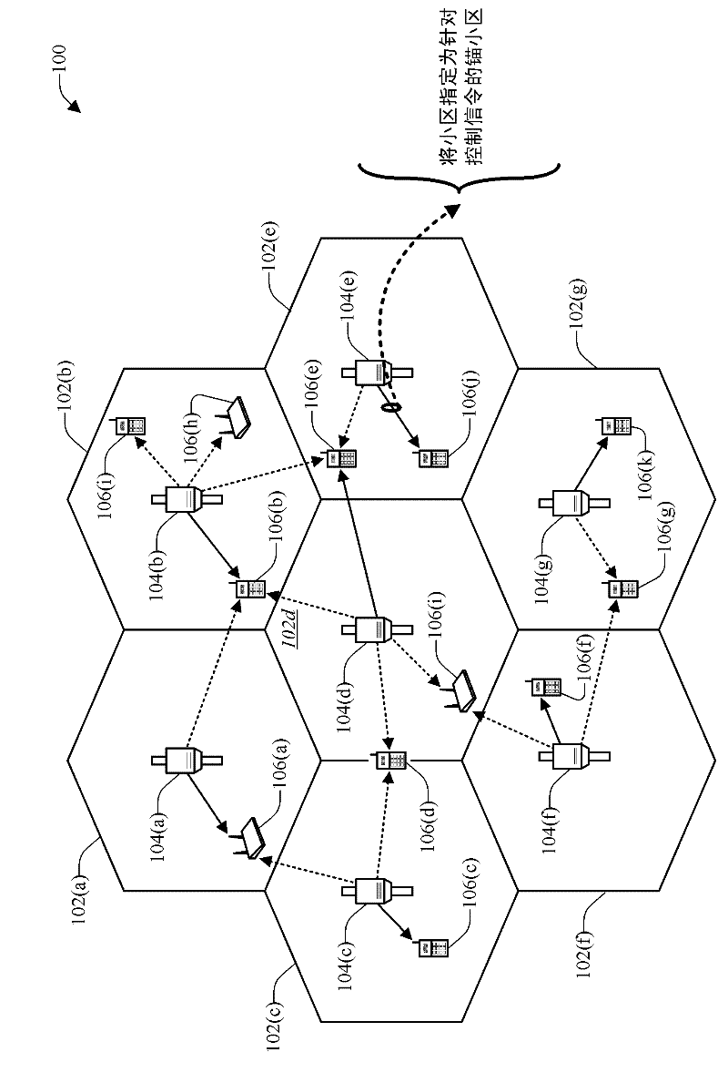
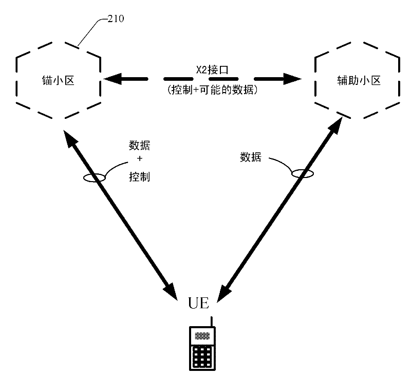
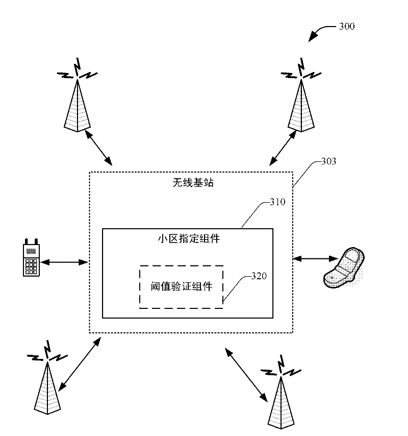
[0033] Embodiments are now described with reference to the figures. In the following description, for purposes of explanation, numerous specific details are set forth in order to provide a thorough understanding of one or more embodiments. It may be evident, however, that the described embodiments may be practiced without these specific details.

[0034] As used in this application, "component," "module," "system" and similar terms include computer-related entities such as, but not limited to, hardware, firmware, a combination of hardware and software, software, or software in execution. . For example, a component may be, but is not limited to being, a process running on a processor, a processor, an object, an executable, a thread of execution, a program, and / or a computer. As examples, both an application running on a computing device and the computing device can be components. One or more components can reside within a process and / or thread of execution and a component ca...


PUM


Abstract

Systems and methods that designate a control attachment point(s) during transmission of data in a Coordinated Multipoint (CoMP) system. The control attachment point is represented by an anchor cell to address control signaling and represent a User Equipment's (UE) interaction with the wireless communication system from a perspective of control (e.g., supplying / sending grants to the UE, transmitting / receiving ACKS on the downlink / uplink to the UE, control information (CQI), and the like.) The cells can further engage in backhaul transfer of information therebetween, and dynamic switching / change of anchor point based on criteria such as control loading, channel quality, and the like can further be implemented.

Description

[0001] Claiming Priority Based on 35 U.S.C. §119 [0002] This patent application claims priority to Provisional Application No. 61 / 108,297, filed October 24, 2008, entitled "ANCHOR CELL FOR NETWORK MIMO," which is assigned to the assignee of this application, and is hereby assigned to It is expressly incorporated into this application by reference. technical field [0003] In general, the following description relates to wireless communications and, in particular, to control signaling in a Coordinated Multipoint (CoMP) system. Background technique [0004] In order to provide various types of communication content such as voice, data, etc., wireless communication systems are widely deployed. A typical wireless data system may be a multiple-access system capable of supporting communication with multiple users by sharing available system resources (eg, bandwidth, transmit power, . . . ). Examples of such multiple-access systems may include Code Division Multiple Access (CDM...

Claims


Application Information

Patent Timeline
Patent Type & Authority Applications(China)
IPC IPC(8): H04W36/18H04B7/02
CPCH04W36/0055H04L1/0026H04L5/0035H04L1/1607H04W36/18H04W36/0069H04B7/02H04W92/20H04W88/08
Inventor R·保兰基A·Y·戈罗霍夫N·布尚
Owner QUALCOMM INC
Why Eureka
Try Eureka