Particle number measurement method

A method of measurement, a technique for particles, used in measurement devices, measurement of scattering properties, analysis of individual particles, etc.

Inactive Publication Date: 2011-09-21
TOKYO ELECTRON LTD
View PDF8 Cites 6 Cited by
  • Summary
  • Abstract
  • Description
  • Claims
  • Application Information

AI Technical Summary

Problems solved by technology

[0008] However, there are cases where particles of several tens of nanometers are generated for reasons other than specific reasons.

Method used


Image

  • Particle number measurement method
  • Particle number measurement method
  • Particle number measurement method

Examples


Embodiment Construction

[0038] Hereinafter, embodiments of the present invention will be described in detail with reference to the drawings.

[0039] First, the particle number measurement method according to the first embodiment of the present invention will be described.

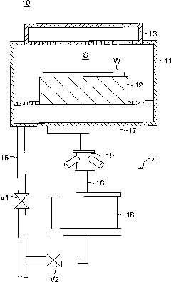
[0040] figure 1 It is a cross-sectional view schematically showing the structure of a substrate processing apparatus to which the method for measuring the number of particles according to this embodiment is applied. This substrate processing apparatus performs a plasma etching process on a semiconductor device wafer (hereinafter simply referred to as "wafer") as a substrate.

[0041] exist figure 1 Among them, the substrate processing apparatus 10 has a chamber 11 (processing chamber). The chamber 11 accommodates a wafer W. A cylindrical susceptor 12 is disposed in the chamber 11. The upper part of the chamber 11 is separated from the A disc-shaped showerhead (showerhead) 13 is disposed so as to face the base 12 . In addition...


PUM


Abstract

There is provided a particle number measurement method capable of accurately measuring the number of particles generated by a specific factor. When the number of particles is measured by irradiating laser beam 25 into a main exhaust line 16 via a glass window 24, receiving lights (L1 and L2) scattered from particles (P1 and P2) crossing with the laser beam 25 by a photodetector 21, and calculating the number of particles based on the received scattered light, static particles P2 are considered as contaminants attached to the glass window 24 and the number of static particles P2 is subtracted from the measured number of particles within the main exhaust line 16.

Description

technical field [0001] The present invention relates to a method for measuring the number of particles, and more particularly to a method for measuring the number of particles by receiving scattered light generated by particles irradiated with laser light to measure the number of particles. Background technique [0002] Conventionally, in substrate processing apparatuses that process wafers, the number of particles moving inside the processing chamber and the exhaust pipe is measured in order to grasp the conditions inside the processing chamber and the exhaust pipe. ISPM (In Situ Particle Monitor: In Situ Particle Monitor) is generally used for the measurement of the number of particles. The ISPM has at least a laser oscillator and a photodetector, converts the received scattered light into an electrical signal, and measures the number of particles based on the intensity of the electrical signal. The photodetector receives scattered light generated from the particles when ...

Claims


Application Information

Patent Timeline
Patent Type & Authority Applications(China)
IPC IPC(8): G01N15/10
CPCG01N21/00G01N2015/1486G01N2015/0046G01N15/06G01N21/94G01N15/0205G01N15/0211G01N15/075G01N15/00G01N15/14G01N21/47G01N21/85
Inventor 长池宏史
Owner TOKYO ELECTRON LTD
Why Eureka
Try Eureka