
Method and device for carrying out electrolytic etching on metal plate

A technology of electrolytic etching and metal plate, applied in electrolytic process, electrolytic components, etc., can solve the problems of reducing product quality and affecting product appearance

Active Publication Date: 2011-09-14
常州正成机电科技有限公司
View PDF6 Cites 7 Cited by
  • Summary
  • Abstract
  • Description
  • Claims
  • Application Information

AI Technical Summary

Problems solved by technology

[0002] The existing continuous electrolytic etching methods and devices for metal plates do not have the process and function of performing electrolytic treatment on metal plates. For example, the patent document of Chinese invention patent application number 200910026641. The method and device of this paper provide a method and device for electrolytic etching of metal plates that are not prone to short circuits and have high etching efficiency.
When using this method and device to process the metal plate, due to the cathode adsorption effect of the metal plate during the electrolysis process, the reverse side and / or part of the front side of the metal plate will absorb black hanging ash, which seriously affects the product. Appearance, reducing product quality
In addition, when the electrolytic roughening treatment of the entire metal plate is carried out, and when the electrolytic polishing process is performed on the entire metal plate, the reverse side of the metal plate will also absorb black hanging dust, which seriously affects the appearance of the product

Method used


Image

  • Method and device for carrying out electrolytic etching on metal plate
  • Method and device for carrying out electrolytic etching on metal plate
  • Method and device for carrying out electrolytic etching on metal plate

Examples


Embodiment Construction

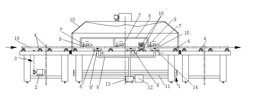
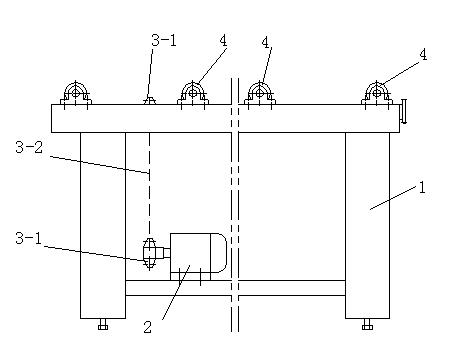
[0034] Such as figure 1 , 2 , 5, 6, 7, and 8, the method for electrolytic etching of metal plates of the present invention comprises the following steps: a, the metal plate 18 having an anti-electrolytic etching graphic layer on the upper surface is placed on the conveying roller 4 or On the conveyor belt; b, the metal plate 18 is moved to the electrolysis zone by the conveyor roller 4 or the conveyor belt; c, at least one negative electrode 7 is on the top as the upper electrode in the electrolysis zone, and at least one positive electrode 6 is on the bottom as the first bottom electrode, And the above-mentioned negative electrode 7 and positive electrode 6 are vertically misplaced, and the metal plate 18 is moved so that the upper surface of the metal plate 18 faces the negative electrode 7 and keeps a certain gap with the negative electrode 7; the lower surface of the metal plate 18 faces the negative electrode 7. Touch the positive electrode 6 and keep a certain gap betwe...


PUM


Abstract

The invention discloses a method and device for carrying out electrolytic etching on a metal plate. The method comprises the following steps: putting a metal plate onto a delivery roll, and delivering to an electrolysis region; arranging at least one negative electrode above the electrolysis region to serve as an upper electrode, and arranging at least one positive electrode below the electrolysis region to serve as a first lower electrode, wherein the upper electrode and the first lower electrode are staggered in the vertical direction; injecting electrolyte into the clearance between the upper surface of the metal plate and the negative electrode, and simultaneously injecting electrolyte into the clearance between the lower surface of the metal plate and the positive electrode; and applying a voltage to conduct the positive electrode and the negative electrode through the electrolyte and the metal plate, wherein the discharging part is provided with an ash-removing negative electrode which is used as a second lower electrode to carry out ash-removing electrolytic treatment on the lower surface of the metal plate. The device comprises a framework, a motor, a transmission gear, the delivery roll, the positive electrode and the negative electrode, wherein at least one ash-removing negative electrode is arranged at the discharging side of the positive electrode close to the discharging part of the metal plate on the framework. The invention can be used for carrying out ash-removing treatment on the metal plate in the electrolytic etching process, and has a reasonable structure.

Description

technical field [0001] The invention relates to a method and a device for performing electrolytic etching on a metal plate on a passing conveying device. Background technique [0002] The existing continuous electrolytic etching methods and devices for metal plates do not have the process and function of performing electrolytic treatment on metal plates. For example, the patent document of Chinese invention patent application number 200910026641. The method and device described herein provide a method and device for electrolytically etching pictures and texts on a metal plate that is less prone to short circuit and has high etching efficiency. When using this method and device to process the metal plate, due to the cathode adsorption effect of the metal plate during the electrolysis process, the reverse side and / or part of the front side of the metal plate will absorb black hanging ash, which seriously affects the product. The appearance of the product reduces the quality o...

Claims


Application Information

Patent Timeline
Patent Type & Authority Applications(China)
IPC IPC(8): C25F7/00
Inventor 周丁政
Owner 常州正成机电科技有限公司
Learn More