
Suspended dielectric combline cavity filter

一种梳状线、电介质的技术,应用在在空腔上悬挂陶瓷谐振器的结构领域,能够解决昂贵、费时、使用复杂等问题

Inactive Publication Date: 2011-08-24
ALCATEL LUCENT SAS
View PDF5 Cites 15 Cited by
  • Summary
  • Abstract
  • Description
  • Claims
  • Application Information

AI Technical Summary

Problems solved by technology

Unfortunately, both the plating and welding steps involve the use of complex metallurgical techniques which are expensive and time consuming

Method used


Image

  • Suspended dielectric combline cavity filter
  • Suspended dielectric combline cavity filter
  • Suspended dielectric combline cavity filter

Examples


Embodiment Construction

[0028] Referring now to the drawings, in which like numerals refer to like components or steps, broad aspects of various exemplary embodiments are disclosed.

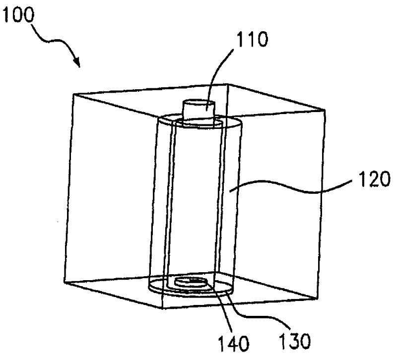
[0029] figure 1 is a perspective view of an exemplary suspended TM mode dielectric combline cavity 100 . In various exemplary embodiments, cavity 100 includes tuning element 110 , resonator 120 , support plate 130 , and mounting element 140 . Cavity 100 is defined by at least one conductive wall. In various exemplary embodiments, such walls may be metallic, or made of metallized polymers.

[0030] In various exemplary embodiments, cavity 100 has a cuboid shape. Therefore, the cavity 100 may include a top surface, a bottom surface and four side walls. As will be apparent to those skilled in the art, cavity resonators may be fabricated in shapes other than cuboids, such as spheres or cylinders, and the like.

[0031] In various exemplary embodiments, tuning element 110 extends downwardly from the top surface of cavit...


PUM


Abstract

A combline filter has a ceramic resonator disposed inside at least one cavitywall. Because the resonator is implemented as a hollow rod, a tuning element may be inserted into an opening on 5 the top ofthe rod to tune its frequency. A mounting element, inserted into an opening on the bottomofthe rod secures its position inside a cavity resonator. Instead of soldering the resonator to the filter's walls, the resonator is supported above a bottom or side wall of the cavityresonator.

Description

technical field [0001] The present invention relates generally to combline filters for microwave and radio frequency signals, and more particularly to structures for suspending ceramic resonators on cavities. Background technique [0002] Coaxial combline filters are widely used in wireless communication systems. More specifically, these devices are often used to filter out unwanted frequencies. When implemented as a bandpass filter, the user can tune the combline filter to select a desired frequency range, called the passband, and discard signals from frequency ranges above or below the desired range. Such filters are often referred to as combline filters because they comprise a series of parallel structures similar to the teeth on a comb. [0003] Cavity resonators confine electromagnetic radiation within a solid structure, usually formed as a cuboid. Since this cavity acts as a waveguide, the pattern of electromagnetic waves is limited to those waves that can fit withi...

Claims


Application Information

Patent Timeline
Patent Type & Authority Applications(China)
IPC IPC(8): H01P7/10H01P1/208
CPCH01P7/10H01P1/2084
Inventor H·R·塞尔希T·M·卢卡里拉
Owner ALCATEL LUCENT SAS
Learn More