
Dielectric barrier discharge plasma swirling device

A dielectric barrier discharge, plasma technology, applied in the direction of plasma, electrical components, gas fuel burners, etc., can solve the problems of unstable combustion and difficult ignition, and achieve reliable ignition and stable combustion, low power consumption, and flow loss. small effect

Active Publication Date: 2011-08-24
江苏中国科学院能源动力研究中心 +1
View PDF6 Cites 32 Cited by
  • Summary
  • Abstract
  • Description
  • Claims
  • Application Information

AI Technical Summary

Problems solved by technology

[0011] The purpose of the present invention is to provide a dielectric barrier discharge plasma swirl device, which helps to solve the problems of difficult ignition and unstable combustion when gas turbines burn low calorific value gases

Method used


Image

  • Dielectric barrier discharge plasma swirling device
  • Dielectric barrier discharge plasma swirling device
  • Dielectric barrier discharge plasma swirling device

Examples


Embodiment Construction

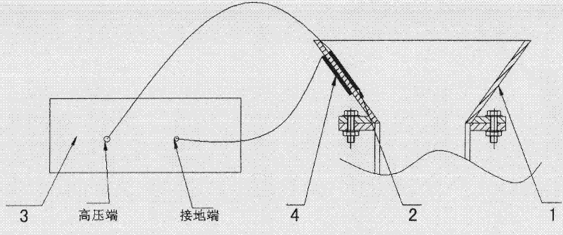
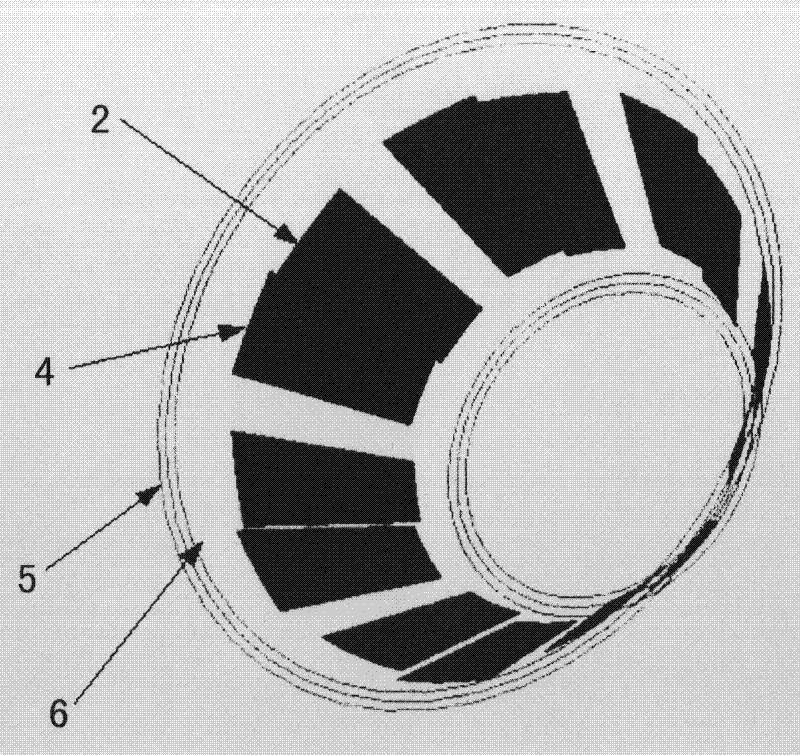
[0039] The dielectric barrier discharge plasma cyclone device of the present invention includes multiple sets of plasma exciters, a combustion stabilizing cone cover and a high-voltage alternating current power supply. The two electrodes of each group of plasma exciter form an electrode pair. These two electrodes are respectively arranged on both sides of the combustion stabilization cone, and can also be arranged evenly on both sides of the combustion stabilization cone. One of the electrodes is connected to the high voltage of the high voltage power supply. The other electrode is connected to the ground terminal of the high-voltage electrode. The electrode arrangement of each electrode pair makes the rotation direction of the plasma-induced flow the same as the air swirl direction. After the high-voltage power is turned on, the air near the plasma exciter is ionized. Generates active free radicals while accelerating the nearby air.

[0040] Describe in detail below in conjun...


PUM

PropertyMeasurementUnit
Thicknessaaaaaaaaaa
Widthaaaaaaaaaa

Abstract

The invention discloses a dielectric barrier discharge plasma swirling device which mainly comprises a stable-combustion conical cover, multiple groups of plasma exciters and a high-voltage power supply, wherein the stable-combustion conical cover is placed at an exit of a burner nozzle; two electrodes of the plasma exciters form an electrode pair and are alternately arranged at the two sides of the stable-combustion conical cover; the electrode in contact with the flame side, of the stable-combustion conical cover is a bare electrode which is connected with a high-voltage end of a high-voltage power supply; the electrode at the other side of the stable-combustion conical cover is a buried electrode which is connected with a grounding end of the high-voltage electrode; the metal electrode arrangement manner of the bare electrode and the buried electrode in each electrode pair enables that the rotation direction of the plasma induced flow is the same as the air swirling direction; and after the high-voltage power is connected, air close to the plasma exciters is ionized to generate active free radicals and accelerate the air nearby. The dielectric barrier discharge plasma swirling device disclosed by the invention has the advantages of simple and compact mechanism, quick response, low energy consumption and the like.

Description

technical field [0001] The invention relates to the field of advanced combustion technology, in particular, it is a combustion-supporting device for improving gas fuel combustion efficiency and combustion stability, which can be used in aviation, chemical industry, power generation, metallurgy and other industries. In particular, it relates to a device for stabilizing and supporting combustion of dielectric barrier discharge plasma. Background technique [0002] Some gaseous fuels with low calorific value are produced in the production process of chemical industry, petroleum industry and iron and steel industry. Taking blast furnace gas as an example, it is the associated gas produced in the ironmaking process, and contains combustible components CO, H 2 less, while the inert gas CO 2 , N 2 More, calorific value is only 2.5 ~ 3.5MJ / Nm 3 . The problems encountered by gas turbines when burning blast furnace gas are: [0003] 1) Low calorific value makes ignition difficul...

Claims


Application Information

Patent Timeline
IPC IPC(8): F23D14/70H05H1/24
Inventor 李钢徐燕骥邵卫卫胡宏斌聂超群朱俊强
Owner 江苏中国科学院能源动力研究中心
Learn More