Variable damping shock absorber and drum washing machine using shock absorber
A shock absorber and variable damping technology, applied in shock absorbers, other washing machines, springs/shock absorbers, etc., can solve problems such as difficult control and realization, insignificant effect, and inaccurate control of damping force
- Summary
- Abstract
- Description
- Claims
- Application Information
AI Technical Summary
Problems solved by technology
Method used
Image
Examples
Embodiment 1
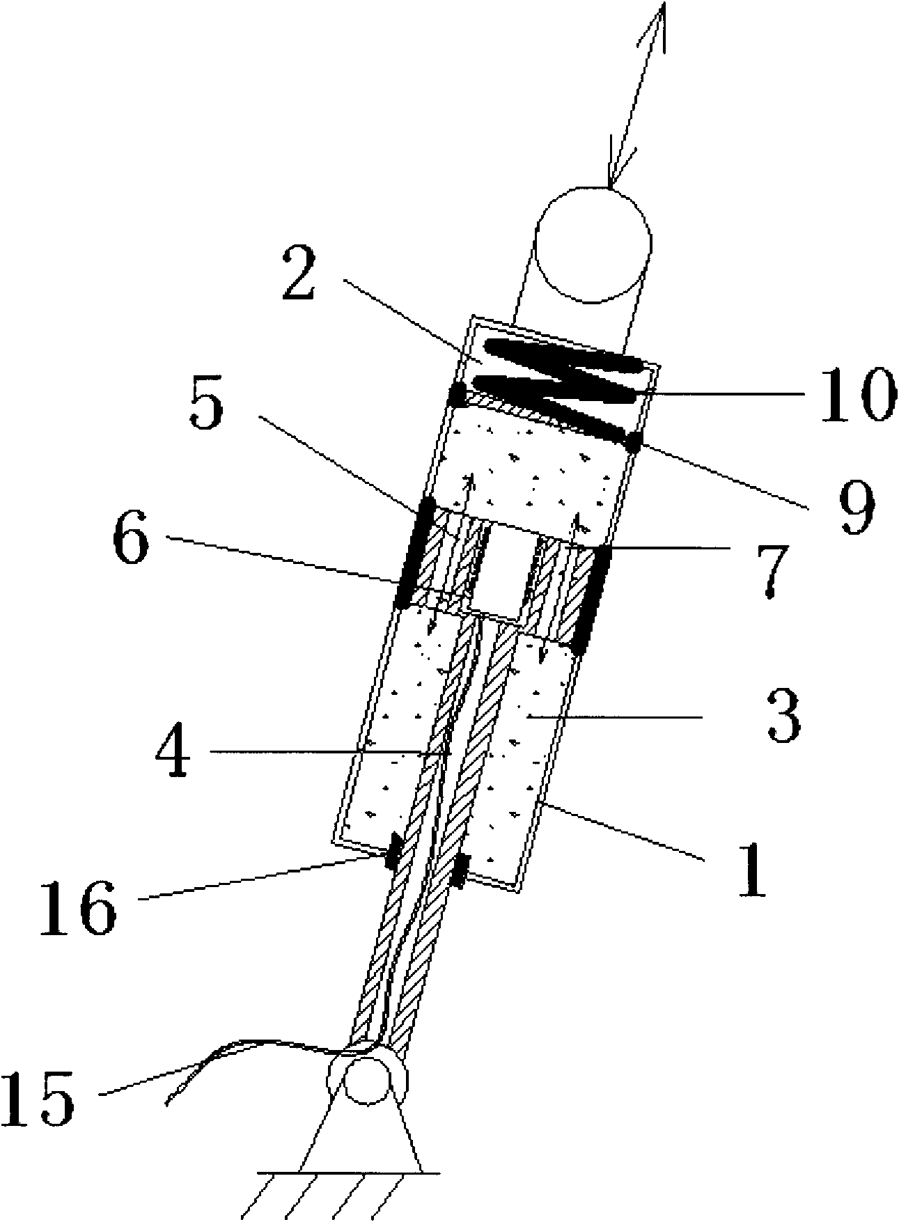
[0063] like figure 1 The shock absorber shown includes: a shock absorber cylinder 1 composed of a damping chamber 3 and a buffer chamber 2; a piston rod 4 inserted into the cylinder 1; a piston 5 fixedly arranged on the piston rod 4 in the damping chamber 3 , the buffer chamber 2 communicates with the outside world; the damping chamber 3 is filled with magnetic fluid, the piston 5 is provided with an electromagnet 6 and a throttle hole 7 for the flow of the magnetic fluid, the electromagnet 6 is connected to the main body through the wire 15 in the piston rod 4 The controller (not shown in the figure) is connected, and the main controller controls the size of the current and uses the change of the magnetic strength of the electromagnet 6 to change the fluidity of the magnetic fluid so as to adjust the damping in real time.
[0064] The shock absorber cylinder 1 is divided into a damping chamber 3 and a buffer chamber 2 by a partition ring 8 fixed on the side wall of the cylind...
Embodiment 2
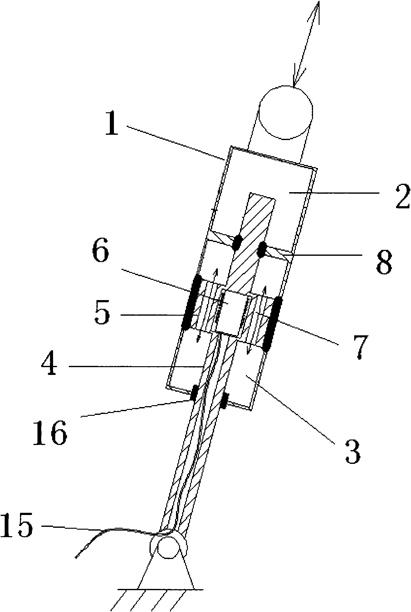
[0067] like figure 2 The shock absorber shown includes: a shock absorber cylinder 1 composed of a damping chamber 3 and a buffer chamber 2; a piston rod 4 inserted into the cylinder 1; a piston 5 fixedly arranged on the piston rod 4 in the damping chamber 3 , the buffer chamber 2 communicates with the outside world; the damping chamber 3 is filled with magnetic fluid, the piston 5 is provided with an electromagnet 6 and a throttle hole 7 for the flow of the magnetic fluid, the electromagnet 6 is connected to the main body through the wire 15 in the piston rod 4 The controller (not shown in the figure) is connected, and the main controller controls the size of the current and uses the change of the magnetic strength of the electromagnet 6 to change the fluidity of the magnetic fluid so as to adjust the damping in real time.
[0068] The shock absorber cylinder 1 is divided into a damping chamber 3 and a buffer chamber 2 by a slidable partition 9 , and the piston 5 is arranged ...
Embodiment 3
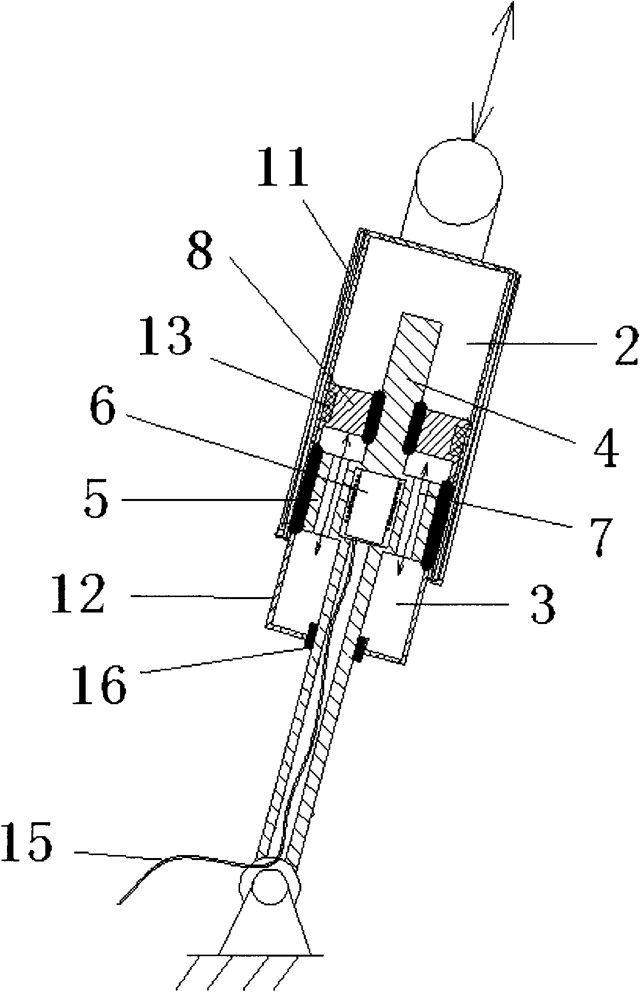
[0070] like image 3 The shock absorber shown includes: a shock absorber cylinder 1 composed of a damping chamber 3 and a buffer chamber 2; a piston rod 4 inserted into the cylinder 1; a piston 5 fixedly arranged on the piston rod 4 in the damping chamber 3 , the buffer chamber 2 communicates with the outside world; the damping chamber 3 is filled with magnetic fluid, the piston 5 is provided with an electromagnet 6 and a throttle hole 7 for the flow of the magnetic fluid, the electromagnet 6 is connected to the main body through the wire 15 in the piston rod 4 The controller (not shown in the figure) is connected, and the main controller controls the size of the current and uses the change of the magnetic strength of the electromagnet 6 to change the fluidity of the magnetic fluid so as to adjust the damping in real time.
[0071] The shock absorber cylinder 1 is composed of a damping cavity shell 12 and a slidable buffer cavity shell 11 sleeved outside the end of the damping...
PUM
 Abstract
Description
Claims
Application Information
 - R&D
- Intellectual Property
- Life Sciences
- Materials
- Tech Scout
- Unparalleled Data Quality
- Higher Quality Content
- 60% Fewer Hallucinations
Browse by: Latest US Patents, China's latest patents, Technical Efficacy Thesaurus, Application Domain, Technology Topic, Popular Technical Reports.
© 2025 PatSnap. All rights reserved.Legal|Privacy policy|Modern Slavery Act Transparency Statement|Sitemap|About US| Contact US: help@patsnap.com


