Cooling device in t-bar hot-rolling line, and t-bar manufacturing facility and manufacturing method

A technology of cooling device and manufacturing equipment, applied in workpiece cooling device, manufacturing tool, metal rolling, etc., can solve problems such as hindering T-section steel, unable to solve cooling bending, etc., and achieve the effect of reducing equipment cost and simplifying equipment structure

Active Publication Date: 2011-08-17
JFE STEEL CORP
View PDF4 Cites 3 Cited by
  • Summary
  • Abstract
  • Description
  • Claims
  • Application Information

AI Technical Summary

Problems solved by technology

[0020] Due to the above reasons, in the conventional manufacturing method of T-shaped steel based on hot rolling, the problem of cooling bending due to the temperature difference between the flange and the web cannot be solved, and it hinders the manufacture of T-shaped steel by hot rolling.

Method used


Image

  • Cooling device in t-bar hot-rolling line, and t-bar manufacturing facility and manufacturing method
  • Cooling device in t-bar hot-rolling line, and t-bar manufacturing facility and manufacturing method
  • Cooling device in t-bar hot-rolling line, and t-bar manufacturing facility and manufacturing method

Examples


Embodiment

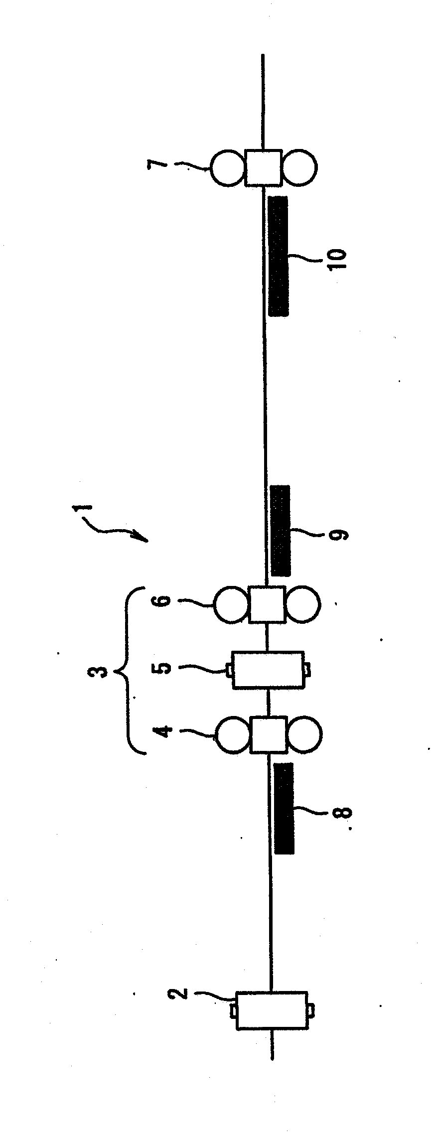
[0097] As a first example, using figure 1 The illustrated T-shaped steel manufacturing facility 1 rolls a T-shaped steel with target dimensions of web height 300 mm, flange width 100 mm, web thickness 9 mm, and flange thickness 16 mm from a steel ingot having a rectangular cross-section with a thickness of 250 mm and a width of 310 mm.

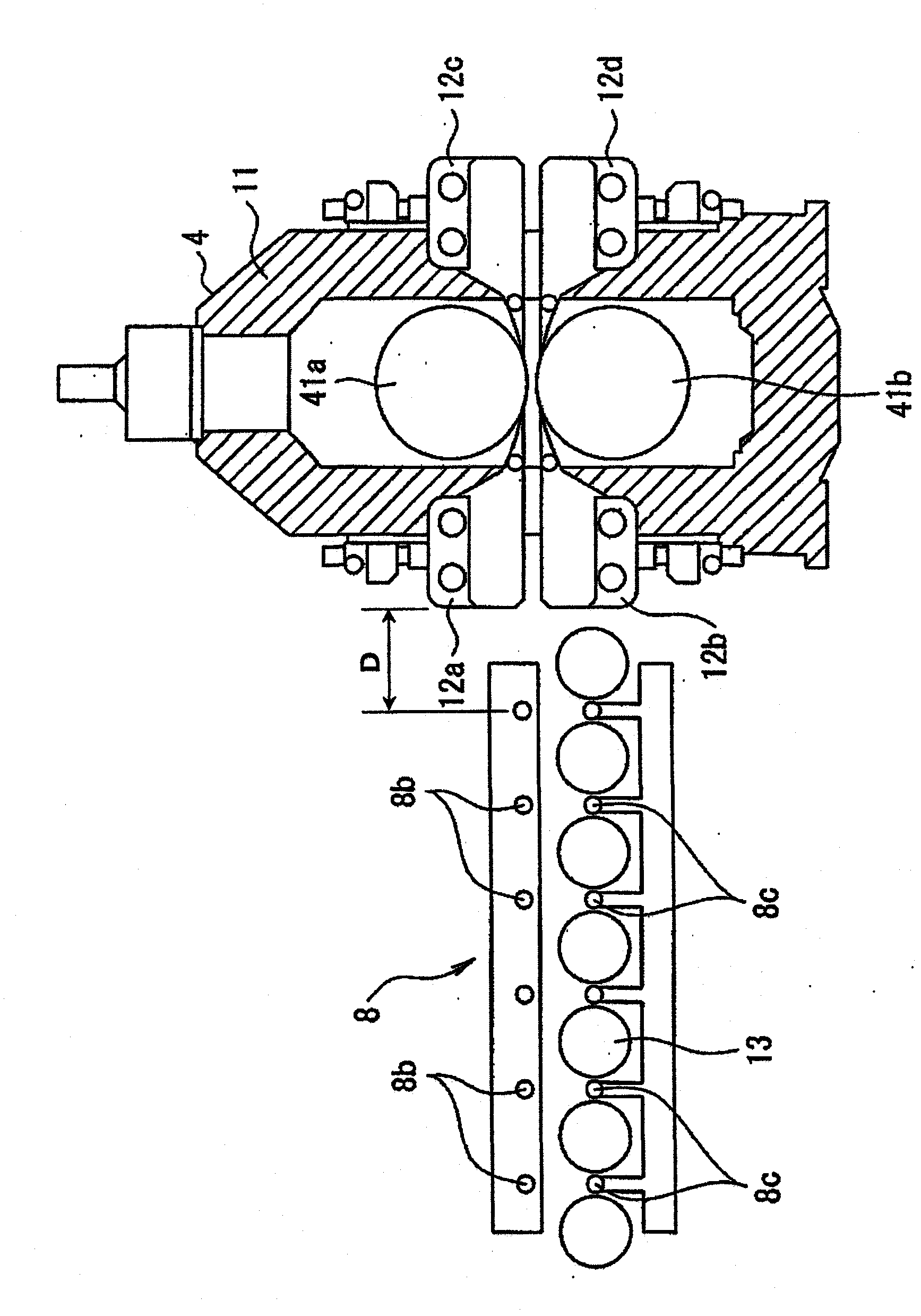
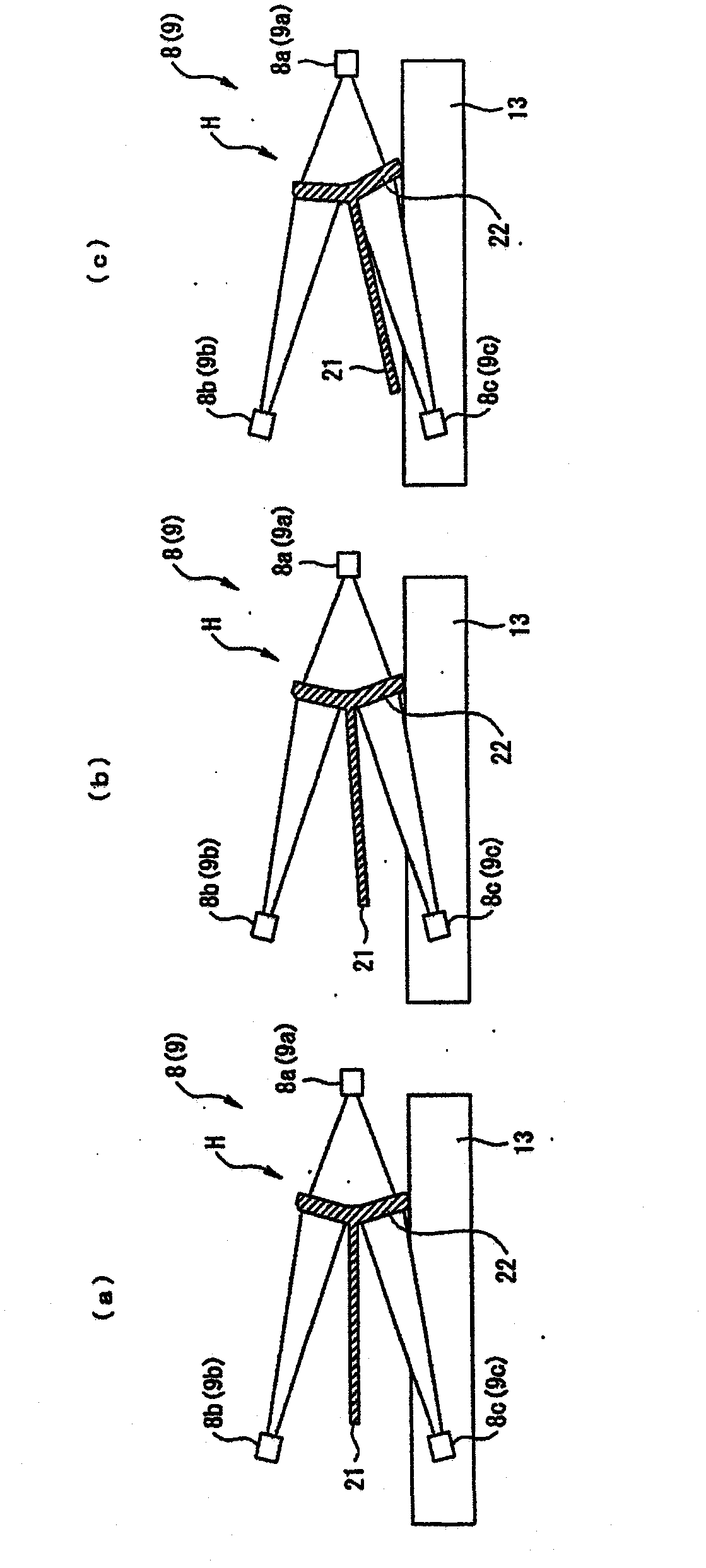
[0098] Such as figure 1 As shown, cooling devices 8, 9, 10 are provided before and after the intermediate rolling group 3 and in front of the finishing mill (universal finishing mill) 7. These cooling devices are arranged close to the outside of the rolling mill main body, and the distance D between the rolling mill main body and the cooling devices is 3 m. The spraying direction of the water-cooling nozzles (8a, 9a, etc.) on the outer surface of the flange is 10° downward relative to the horizontal direction. In addition, it is configured to be mounted on a side guide that guides the material H to be rolled to the side of the flange 22 of...


PUM

PropertyMeasurementUnit
yield stressaaaaaaaaaa

Abstract

A cooling device (8) in a T-bar hot-rolling line is capable of minimizing camber due to cooling, which is caused by the temperature difference between a flange and a web, and the cooling device is provided with an outer surface water-cooling nozzle (8a) for cooling the flange outer surface of a material to be rolled (H) comprising approximately T-shaped cross-sectional web (21) and flange (22) by water cooling, and / or an inner surface water-cooling nozzle for cooling the flange inner surface of the material to be rolled by water cooling. The outer surface water-cooling nozzle and / or the inner surface water-cooling nozzle are / is provided in the position and direction where the nozzle(s) can inject water toward the outer surface and / or the inner surface of the flange in any inclined state of the web of the material to be rolled when the web is inclined from the state in which the web is approximately horizontal to a roller table (13) for carrying the material to be rolled to the state in which the tip of the web and the lower end of the flange are on the same level.

Description

technical field [0001] The present invention relates to a cooling device, manufacturing equipment, and manufacturing method when manufacturing T-shaped steel (T-bar) by hot rolling. Background technique [0002] Figure 11 Indicates the cross-sectional shape of the T-shaped steel. The T-shaped steel 20 is a T-shaped section steel composed of a web (web) 21 and a flange (flange) 22 , and is widely used in fields such as shipbuilding and bridges. T-shaped steel is manufactured into finished products of various sizes according to its use, use conditions, use parts, etc. The size of T-shaped steel 20 commonly used is web height: about 200-1000mm, web thickness: about 8-25mm, web inner dimension: about 190-980mm, flange width: about 80-400mm, flange thickness: 12 ~ 40mm or so. In addition, in the case of T-shaped steel 20 used for shipbuilding, the height of the web is often more than twice the width of the flange. [0003] Generally speaking, the T-shaped steel 20 is manufac...

Claims


Application Information

Patent Timeline
Patent Type & Authority Applications(China)
IPC IPC(8): B21B45/02B21B1/092
CPCB21B45/0215B21B1/092B21B45/0233B21B2045/0221
Inventor 高岛由纪雄高桥英树山口阳一郎中田直树
Owner JFE STEEL CORP
Why Eureka
Try Eureka