
Closed loop wireless energy supply system for implantable medical electronic device

An implantable medical and electronic device technology, which is applied in the fields of electronic information technology and biomedicine, can solve the problems of failing to realize the adjustment of the resonant frequency of coils in the body, failing to obtain the power supply status of implanted devices, and increasing the financial burden of patients' families, etc., to achieve It is beneficial to implant applications, improve adaptability and stability, and achieve flexible and convenient effects

Inactive Publication Date: 2011-08-17
SOUTHEAST UNIV
View PDF5 Cites 82 Cited by
  • Summary
  • Abstract
  • Description
  • Claims
  • Application Information

AI Technical Summary

Problems solved by technology

The disadvantage of this type of energy supply method is that before the energy of the battery is about to run out, a new battery must be re-implanted through surgery. shadow
[0006] At present, most of the implanted medical electronic devices used clinically belong to the open-loop system, that is, they either act on the human body unidirectionally through the implanted system, or extract biological signals from the human body unidirectionally for processing, and cannot telemetry results for feedback control
The Chinese patent "Controllable High-Efficiency Wireless Energy Supply Device for Biological Implants" (application number: 200810036568.3) proposes a high-efficiency wireless energy supply device based on single-chip microcomputer control frequency, which can realize the adjustable frequency of the external transmission module, However, it only adjusts the system frequency in one direction, not only fails to adjust the resonant frequency of the coil in the body, but also fails to obtain the power supply status of the implanted device

Method used


Image

  • Closed loop wireless energy supply system for implantable medical electronic device
  • Closed loop wireless energy supply system for implantable medical electronic device
  • Closed loop wireless energy supply system for implantable medical electronic device

Examples


Embodiment Construction

[0032] The present invention will be described in detail below in conjunction with the accompanying drawings and embodiments, but the protection scope of the present invention should not be limited to the following embodiments.

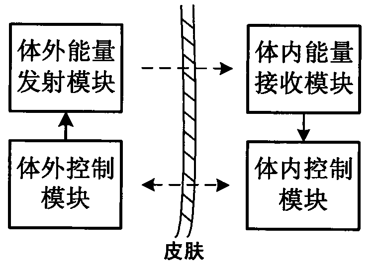
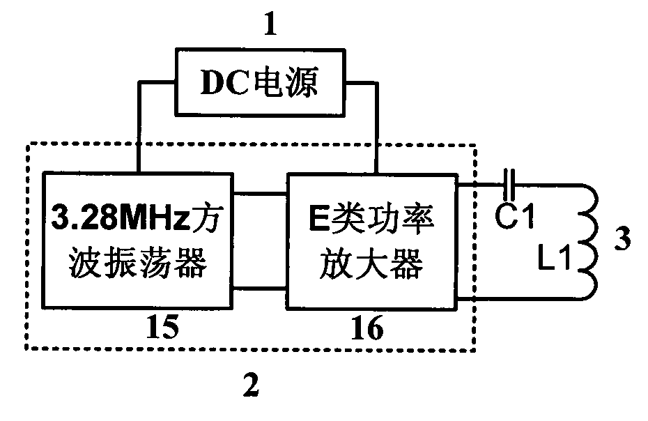
[0033] see figure 1 , 2, the system of the present invention is provided with an external energy transmitting module, an external control module, an internal energy receiving module and an internal control module. The energy transmitting drive circuit 2 in the external energy transmitting module converts the external DC power supply 1 into high-frequency alternating electric energy, and then passes The resonant energy transmitting coil 3 forms an effective electromagnetic field, which is transmitted to the energy receiving coil 4 tuned on the same frequency with maximum efficiency through electromagnetic coupling. The rectification and voltage stabilization circuit 5 converts the alternating electric energy coupled to the energy receiving coil 4 into...


PUM


Abstract

The invention discloses a closed loop wireless energy supply system for an implantable medical electronic device. An in-vitro energy transmission driving circuit converts external DC power into high frequency AC electrical energy, and transmits the high frequency alternating electrical energy to an in-vivo receiving coil tuned on the same frequency in an electromagnetic coupling way by a transmission coil. A rectification voltage stabilizing circuit converts the AC electrical energy obtained from the receiving coil into DC electrical energy, and provides the DC electrical energy for a charging management circuit to charge an in-vivo rechargeable lithium ion battery. An in-vivo charging state monitoring circuit periodically monitors the charging state of the lithium ion battery. The charging state is processed by an in-vivo processor, and the processed charging state is fed back to an in-vitro processor by a radio frequency transceiver circuit, and is displayed on a liquid crystal display (LCD) module. Simultaneously, the in-vitro processor controls the external DC power according to the charging state. Therefore, the closed loop wireless energy supply system can monitor the charging state of the implantable medical device and realize timely feedback and control.

Description

technical field [0001] The present invention relates to electronic information technology and biomedical technology, in particular to a closed-loop wireless energy supply system for implantable medical electronic devices, which is a closed-loop transdermal energy supply system capable of simultaneous wireless energy transmission and monitoring and feedback control of power supply status. Wireless energy supply system. Background technique [0002] With the development of microelectronic information technology and biomedical technology, various implantable medical electronic devices have been widely used in the field of clinical in vivo diagnosis and treatment, and are playing an increasingly important role in the diagnosis and treatment of various diseases. One of the common technical problems of implanting medical electronic devices is how to effectively provide enough energy to implanted electronic devices to maintain their long-term, stable and reliable operation and real...

Claims


Application Information

Patent Timeline
IPC IPC(8): H02J17/00H02J7/02G08C17/02H02J7/00H02J50/12
Inventor 王志功吕晓迎龚鑫
Owner SOUTHEAST UNIV
Learn More