Eureka AIR delivers breakthrough ideas for toughest innovation challenges, trusted by R&D personnel around the world.

Garbage incinerator without dioxin emission

A technology for waste incinerators and furnace bodies, which is applied in incinerators, combustion methods, combustion types, etc., can solve the problems of unavailability of water vapor, air pollution, and labor-intensive feeding.

Inactive Publication Date: 2011-08-17
李献本 +1
View PDF6 Cites 3 Cited by
  • Summary
  • Abstract
  • Description
  • Claims
  • Application Information

AI Technical Summary

Problems solved by technology

This kind of traditional incinerator mainly incinerates garbage, not only the heat energy cannot be fully utilized, but also the toxic and harmful gases produced by the burning of harmful garbage will pollute the air
The "a kind of garbage incinerator" designed by me earlier, the patent application number is 201110044007X, although it solves the serious air pollution problem, but because it is a vertical boiler, and the feeding port is located above the combustion chamber, not only when feeding Uneven distribution is not conducive to complete and complete combustion, and the labor intensity of feeding is high, and a large amount of water vapor cannot be used

Method used


Image

  • Garbage incinerator without dioxin emission
  • Garbage incinerator without dioxin emission
  • Garbage incinerator without dioxin emission

Examples


Embodiment Construction

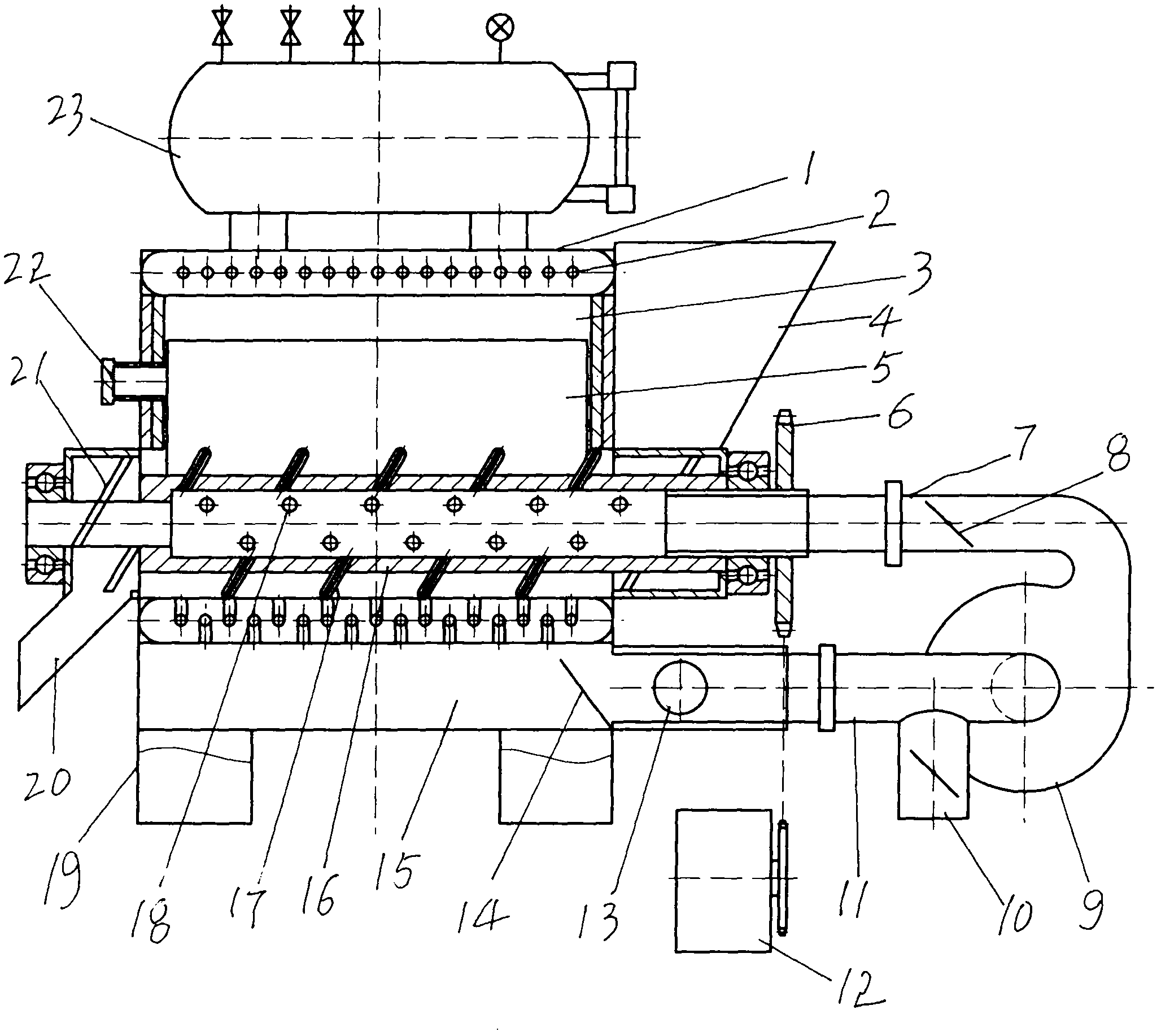
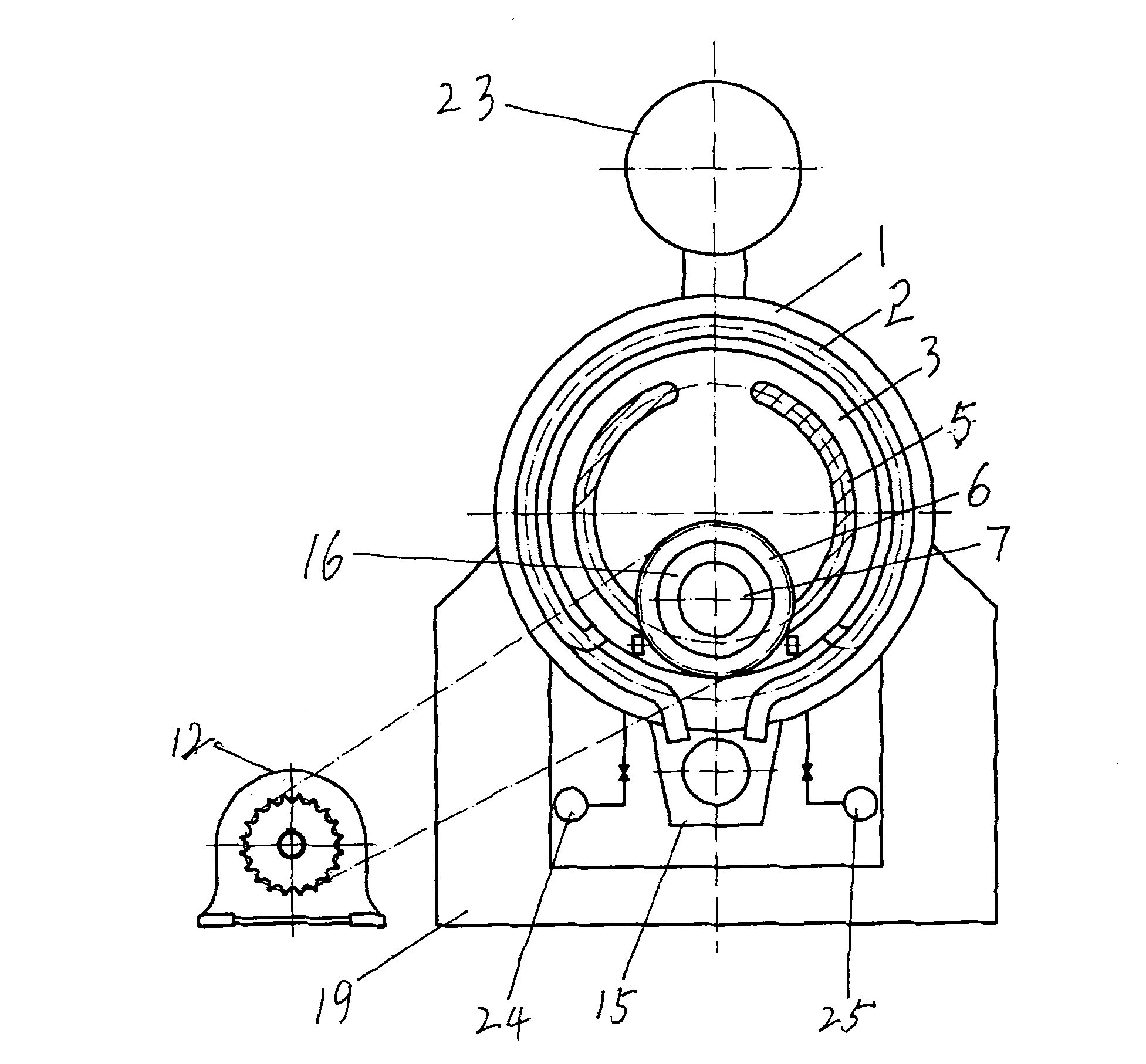
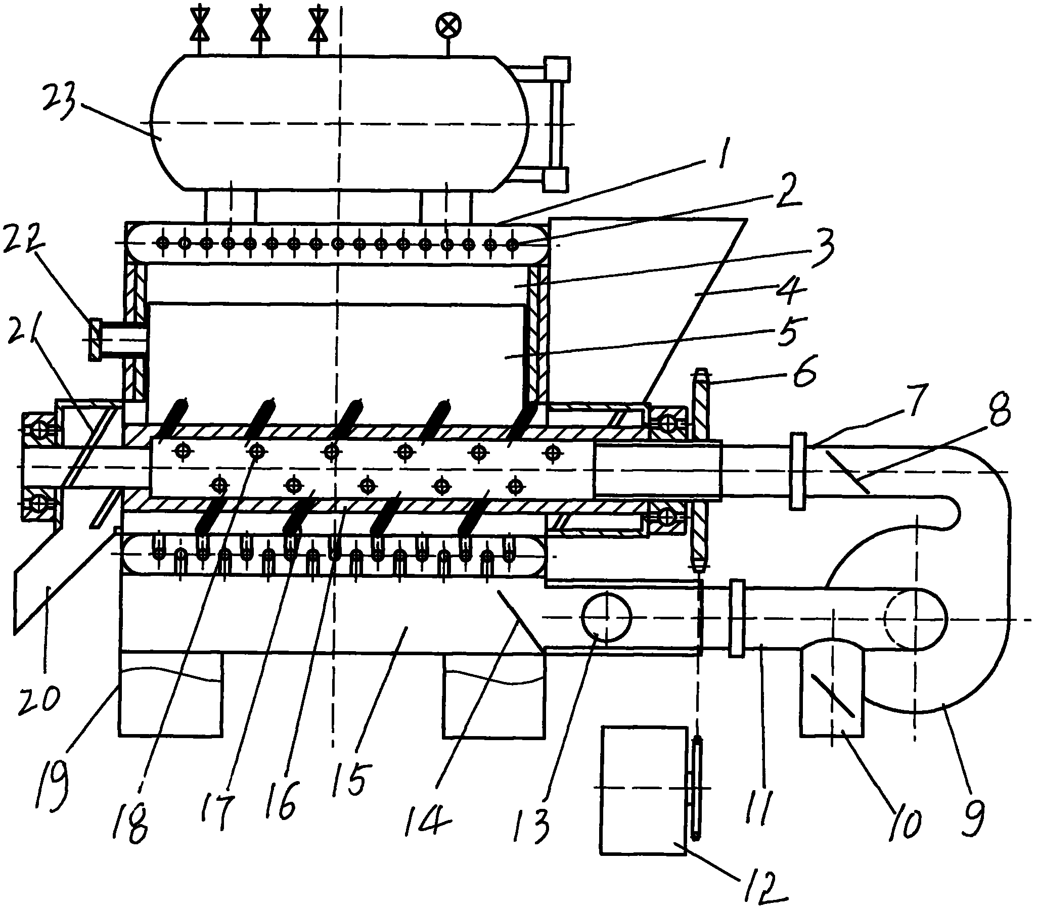
[0007] Describe embodiment in detail in conjunction with accompanying drawing, the present invention is that an annular hot water jacket 1 is installed in the circumferential wall of a horizontal furnace body, and support 19 is installed on the furnace wall on both sides of the bottom of the furnace body, on both sides An ash hopper 15 is installed at the lower part of the furnace body between the supports, a water inlet 25 and a sewage outlet 24 are connected to the hot water jacket at the bottom of the furnace body, and a high-pressure water tank connected to the hot water jacket is installed on the top of the furnace body through a connecting pipe. Steam drum 23, in the combustion chamber in the middle of the furnace body, two arc-shaped fire walls 5 are arranged longitudinally on both sides with the center of the hot water jacket. There is a tempering port in the middle of the top. On the upper surface of the bottom of the hot water jacket between the bottoms of the two fir...


PUM


Abstract

The invention discloses a garbage incinerator without dioxin emission. An ash bucket is arranged between supporting seats of a horizontal furnace body; a high-pressure steam drum communicated with a hot water jacket of the furnace body is arranged on the top of the furnace body; two arc-shaped firewalls are arranged along two longitudinal directions in a combustion chamber; a tempering channel is formed between the outer sides of the two firewalls and the hot water jacket; a tubular axle is rotationally arranged between the bottoms of the two firewalls; one end of the tubular axle extends out of the furnace body; a chain wheel is arranged at one end of the tubular axle, and is connected with a reducing motor; a feed opening close to one side of the chain wheel is communicated with the combustion chamber from the upper side of the tubular axle; the other end of the tubular axle is provided with a slag outlet hopper; air holes communicating inside and outside and poking teeth are uniformly distributed on the circumferential wall of the tubular axle; a row of heat radiating pipes alternatively arranged positively and negatively along the tempering direction are uniformly distributed in the water jacket; the fire inlet of each heat radiating pipe is arranged on the inner wall of the lower side of the water jacket; the other end of each heat radiating pipe is communicated with the ash bucket; a three-way pipe is connected between the ash bucket and the air introducing port of a blower; and regulating plates are arranged in a blowing port and a connecting pipe of the tubular axle. By adopting the garbage incinerator, garbage incineration is more complete, harmful gases such as dioxin are not emitted to the outside, and the aims of protecting the environment and saving energy are fulfilled.

Description

Technical field: [0001] The invention relates to waste incineration equipment, in particular to a dioxin-free waste incinerator which utilizes cyclic combustion in waste incineration, not only does not discharge harmful gas, but also fully utilizes heat energy and residues. Background technique: [0002] At present, the garbage incinerators in cities are all equipped with a charging port above or on one side of the combustion chamber of the furnace body. A door or cover is installed on the charging port. Features a chimney. This kind of traditional incinerator mainly incinerates garbage, not only the heat energy cannot be fully utilized, but also the toxic and harmful gases produced by the burning of harmful garbage will pollute the air. The "a kind of garbage incinerator" designed by me earlier, the patent application number is 201110044007X, although it solves the serious air pollution problem, but because it is a vertical boiler, and the feeding port is located above the...

Claims


Application Information

Patent Timeline
IPC IPC(8): F23G5/00F23G5/44F22B13/04
Inventor 李献本宋建恩杨海军
Owner 李献本
Why Eureka
Eureka Blog
Learn More