Machine tool track swinging mechanism for processing ring-shaped patterns by using electric spark

An electric spark and ring technology, applied in the direction of metal processing machinery parts, metal processing equipment, driving devices, etc., can solve the problems of increasing auxiliary time, increasing manufacturing cost, and reducing processing efficiency, so as to reduce auxiliary time, reduce manufacturing cost, The effect of improving processing efficiency

Active Publication Date: 2013-05-08
苏州电加工机床研究所有限公司
View PDF1 Cites 0 Cited by
  • Summary
  • Abstract
  • Description
  • Claims
  • Application Information

AI Technical Summary

Problems solved by technology

However, in order to perform intermediate and finishing machining on the side of the rough machining pattern cavity, it is necessary to replace multiple electrodes, increase the size of the electrode in the side direction, reduce the discharge gap, and achieve the purpose of trimming the pattern cavity laterally. , but this method will firstly increase the number of electrodes and increase the manufacturing cost, and secondly, due to multiple electrode replacements, the auxiliary time will be increased and the processing efficiency will be reduced

Method used


Image

  • Machine tool track swinging mechanism for processing ring-shaped patterns by using electric spark
  • Machine tool track swinging mechanism for processing ring-shaped patterns by using electric spark
  • Machine tool track swinging mechanism for processing ring-shaped patterns by using electric spark

Examples


Embodiment 1

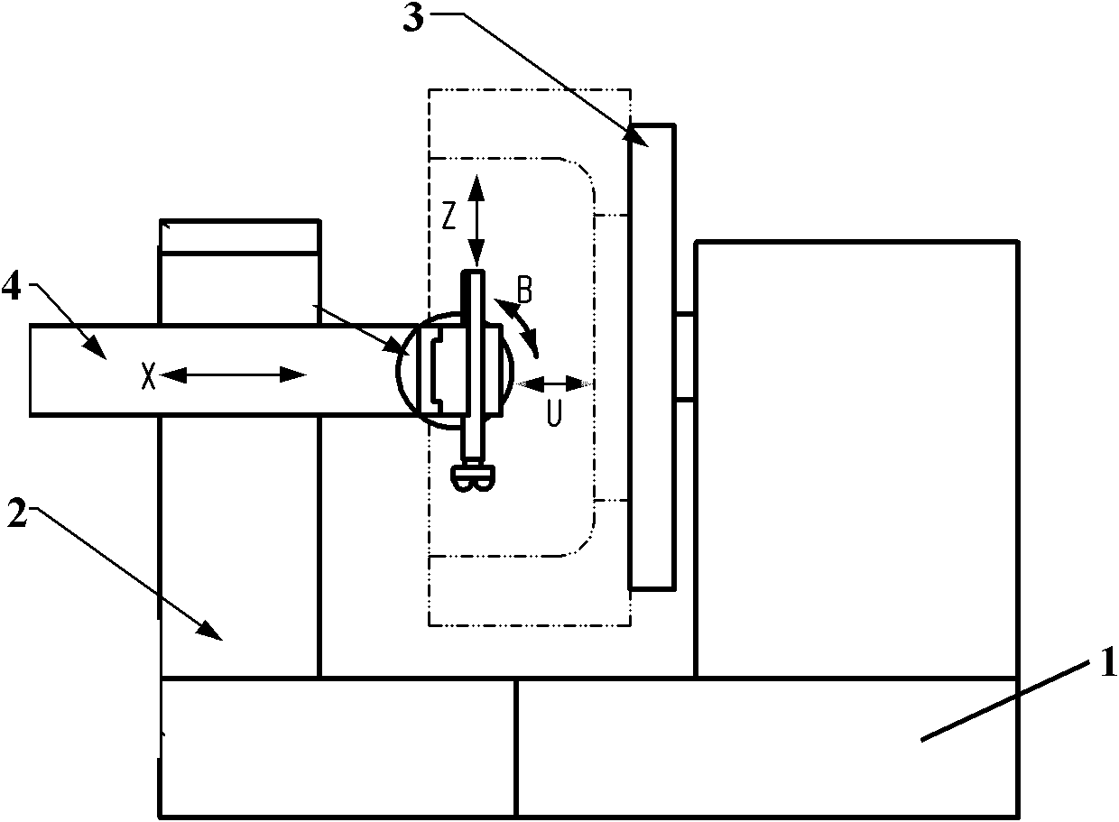
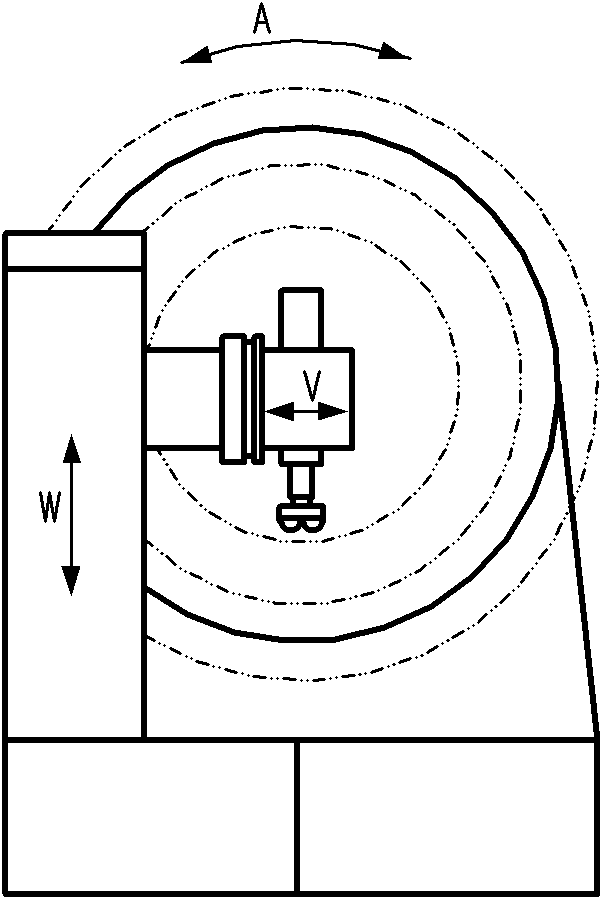
[0032] Embodiment 1: A machine tool trajectory rocking mechanism for EDM circular patterns, as attached Figure 1-4 As shown, it includes: a bed 1, a column cross arm 2 and an A-axis turntable 3 for placing workpieces to be processed. The column cross arm 2 is provided with an X-axis slider 4 that can move along the X-axis direction. The X The shaft slider 4 is connected with the column cross arm 2 through the first guide rail; a B-axis turntable 5 is fixed on one end of the X-axis slider 4, and a U-axis base 6 is fixedly installed on the surface of the B-axis turntable 5; a U-axis slider The block 7 is movably connected with the U-axis base 6 through the second guide rail, and the U-axis slider 7 can move along the X-axis direction;

[0033] A V-axis slider 8 is movably connected with the U-axis slider 7 through the third guide rail, and the V-axis slider 8 can move along the Y-axis direction; a Z-axis slider 9 is movably connected with the V-axis slider through the fourth gu...

Embodiment 2

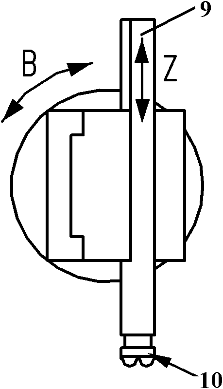
[0036] Embodiment 2: A machine tool trajectory rocking mechanism for EDM circular patterns, as attached Figure 5-8 As shown, it includes: a bed 1, a column cross arm 2 and an A-axis turntable 3 for placing workpieces to be processed. The column cross arm 2 is provided with an X-axis slider 4 that can move along the X-axis direction. The X The shaft slider 4 is connected with the column cross arm 2 through the first guide rail; a B-axis turntable 5 is fixed on one end of the X-axis slider 4, and a U-axis base 6 is fixedly installed on the surface of the B-axis turntable 5; a U-axis slider The block 7 is movably connected with the U-axis base 6 through the second guide rail, and the U-axis slider 7 can move along the X-axis direction;

[0037] A Z-axis slider 9 is movably connected with the U-axis slider 7 through the third guide rail, and the Z-axis slider 9 can move along the Z-axis direction; a V-axis slider 8 is movably connected with the Z-axis slider through the fourth gu...


PUM


Abstract

The invention relates to a machine tool track swinging mechanism for processing ring-shaped patterns by using an electric spark, which comprises a vertical column cross arm, wherein the vertical column cross arm is provided with an X-axis sliding block capable of moving in the X-axis direction; the X-axis sliding block is connected with the vertical column cross arm by a first guide rail; a B-axis rotating disc is fixed at one end of the X-axis sliding block, and a U-axis base is fixedly arranged on the surface of the B-axis rotating disc; a U-axis sliding block is movably connected with the U-axis base by a second guide rail, and can move in the X-axis direction; a V-axis sliding block is movably connected with the U-axis sliding block by a third guide rail, and can move in the X-axis direction; and a Z-axis sliding block is movably connected with the V-axis sliding block by a fourth guide rail and can move in the Z-axis direction, and an electrode is arranged at one end of the Z-axis sliding block. In the machine tool track swinging mechanism, lateral discharge gaps can be effectively compensated by using the single electrode, and no interference is generated between the electrode and a tire mold during processing, so that the purpose of carrying out lateral electric spark finishing on the cavity of the tire mold cavity is achieved.

Description

technical field [0001] The invention relates to a machine tool trajectory rocking mechanism for electric discharge machining annular patterns, which belongs to the field of special electric discharge processing. Background technique [0002] my country's automobile industry is developing rapidly, and the demand for vehicle tires is also growing rapidly. However, foreign brands and joint venture brands account for a large share of the high-end vehicle tire market. Taking 2008 as an example, the global tire sales in 2008 reached 92 billion US dollars , 12 companies with more than 1 billion US dollars accounted for 81% of the global tire sales revenue, but these 12 companies are all foreign companies. In order to adapt to the rapid development of my country's automobile industry, we must speed up the development of my country's tire manufacturing industry. One of the key technologies in the manufacture of high-grade tires is the manufacture of high-grade tire molds, which has b...

Claims


Application Information

Patent Timeline
Patent Type & Authority Patents(China)
IPC IPC(8): B23Q5/02B23H7/00
Inventor 叶军柳建华吴国兴卢智良任忠岩朱红敏曹光林
Owner 苏州电加工机床研究所有限公司
Why Eureka
Try Eureka