RFID tag, RFID tag set and RFID system
A technology of RFID tags and components, applied in the field of RFID tags, can solve problems such as difficult to cover, difficult to achieve high gain, difficult to cover the frequency of use of RFID tags, etc., to achieve the effect of realizing broadband and high gain
- Summary
- Abstract
- Description
- Claims
- Application Information
AI Technical Summary
Problems solved by technology
Method used
Image
Examples
no. 2 approach
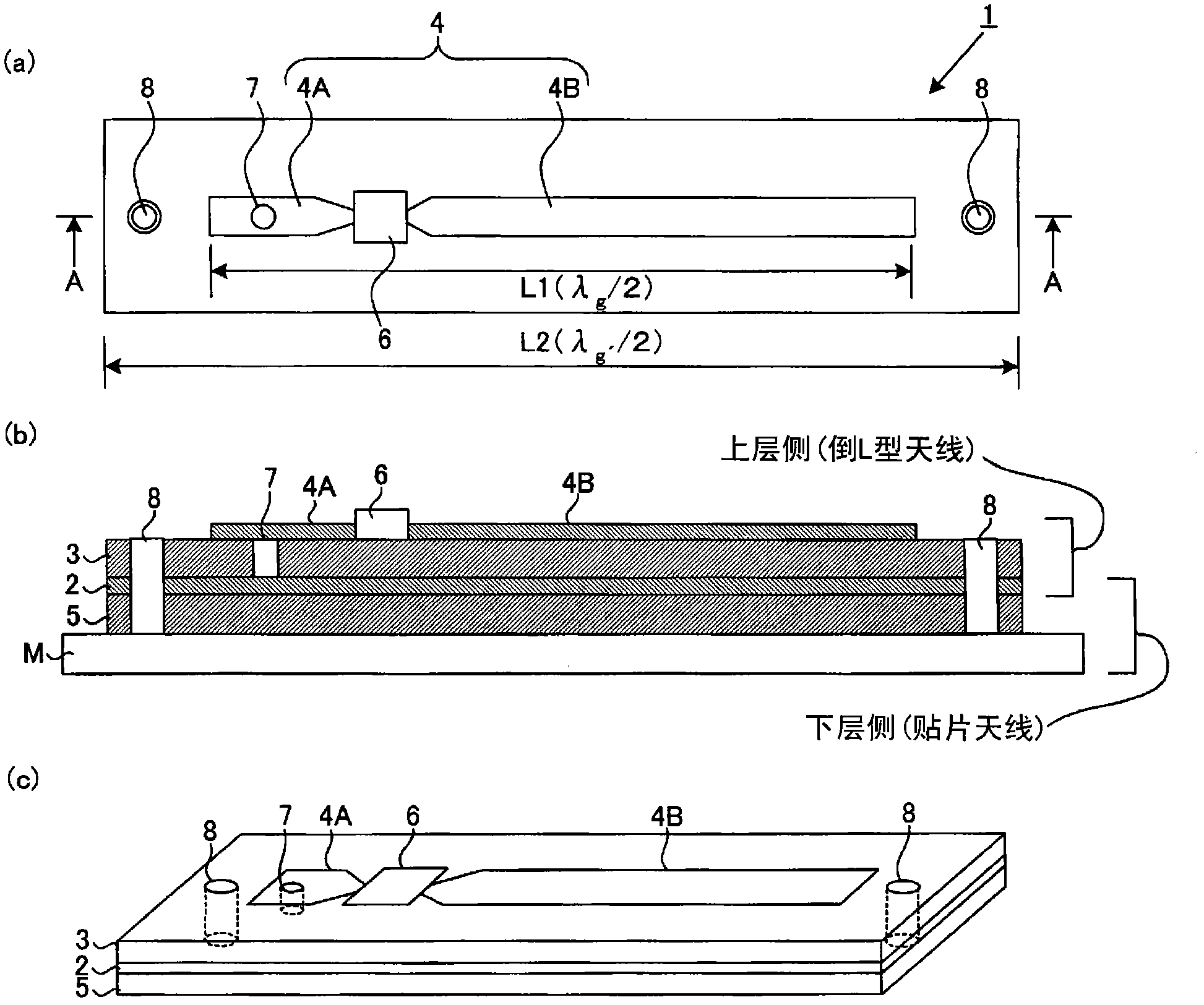
[0042] In the RFID tag 1A according to the second embodiment, the position of the via hole 7 of the RFID tag 1 according to the first embodiment is moved to the second antenna conductor portion 4B side, and connected to the ground conductor plate 2 through the via hole 7. RFID tags. Other configurations are the same as those of the RFID tag 1 .
no. 3 approach
[0044] In the RFID tag 1B according to the third embodiment, unlike the RFID tag 1 according to the first embodiment, the antenna part 4 and the ground conductor plate 2 are not connected through the via hole 7, but the first antenna is formed by bending. One end 40A- 1 of the conductor portion 40A is connected to the first antenna conductor portion 40A and the ground conductor plate 2 . Such a structure can be realized by the following processing. For example, one conductor plate is bent into an angle shape ("U" shape). At this time, the first dielectric substrate 3 is rolled inside. In this state, the upper surface side of the first dielectric substrate 3 is etched to form the first antenna conductor portion 40A and the second antenna conductor portion 4B. In addition, when so constituted, it can be as Figure 4 Mounting holes 8 for mounting the RFID tag 1B on the metal object M are formed at the four corners of the RFID tag 1B in that way.
no. 4 approach to no. 6 approach
[0046] If the structures of the RFID tags of the fourth to sixth embodiments are simplified, the RFID tags 1C and 1D according to the fourth and fifth embodiments are obtained by further processing the shape of the antenna part 4 of the RFID tag 1. Yes, the RFID tag 1E according to the fifth embodiment is obtained by further processing the shape of the ground conductor plate 2 of the RFID tag 1 . In addition, since it is only necessary to know these differences, in Figure 5 to Figure 7 is briefly illustrated.
[0047] Specifically, the RFID tag 1C is different from the above-mentioned RFID tag 1 in that, in the RFID tag 1C, the shape of the second antenna conductor portion is formed into Figure 5 The shown meander-shaped second antenna conductor portion 40B. On the other hand, the difference between the structure of the RFID tag 1D and the above-mentioned RFID tag 1 is that in the RFID tag 1D, a Figure 6 The U-shaped second antenna conductor portion 400B is formed by fol...
PUM
 Abstract
Description
Claims
Application Information
 - Generate Ideas
- Intellectual Property
- Life Sciences
- Materials
- Tech Scout
- Unparalleled Data Quality
- Higher Quality Content
- 60% Fewer Hallucinations
Browse by: Latest US Patents, China's latest patents, Technical Efficacy Thesaurus, Application Domain, Technology Topic, Popular Technical Reports.
© 2025 PatSnap. All rights reserved.Legal|Privacy policy|Modern Slavery Act Transparency Statement|Sitemap|About US| Contact US: help@patsnap.com


