
Gas valve

A gas valve, gas technology, applied in the direction of valve detail, valve device, combustion valve/nozzle/pump, etc.

Inactive Publication Date: 2011-08-03
BSH BOSCH & SIEMENS HAUSGERAETE GMBH
View PDF4 Cites 3 Cited by
  • Summary
  • Abstract
  • Description
  • Claims
  • Application Information

AI Technical Summary

Problems solved by technology

However, this valve has disadvantages in view of the simplicity of production and in view of life

Method used


Image

  • Gas valve
  • Gas valve
  • Gas valve

Examples


Embodiment Construction

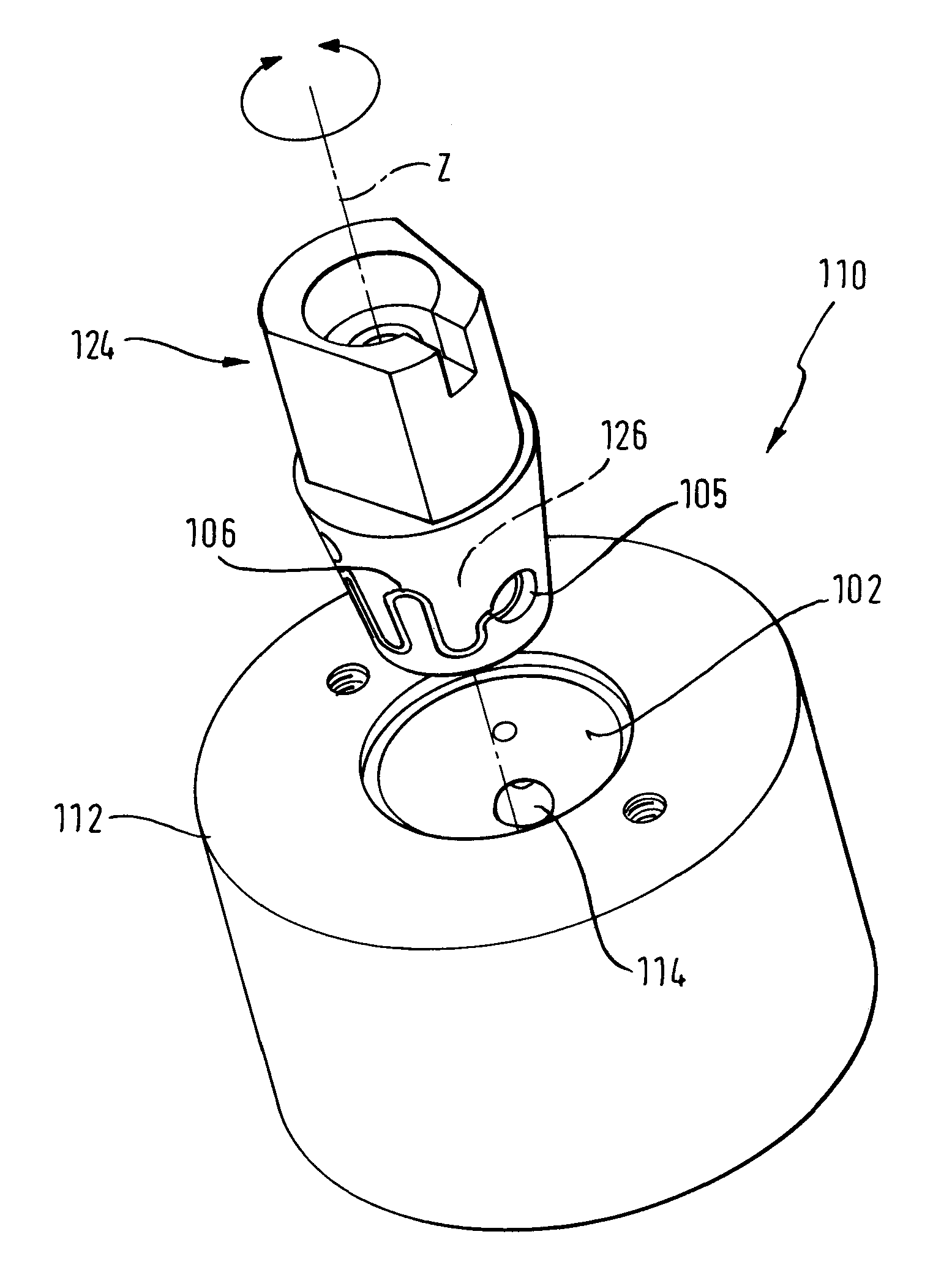
[0027] figure 1 The gas valve 10 is shown in side view. A gas valve 10 is provided for supplying a gas flow to a gas cooking station or a gas burner of a gas oven. The gas valve 10 has a valve body 12 which, in the exemplary embodiment, is of square design and in which an outlet channel 14 is arranged for the gas to flow through. An inlet opening 16 for gas flow into the gas valve 10 and a gas outlet 18 for gas flow to the gas burner are formed on the valve body 12 . Arranged on the upper side 20 of the valve body 12 facing the operator in one application is a guide element 22 which accommodates an adjusting element (not shown) for manually adjusting the gas flow. In the present exemplary embodiment, the gas valve 10 has a conically shaped plug 24 . The plug 24 is rotatably seated in the plug seat hole relative to the valve body 12 . The plug is also designed as a sleeve and has a hollow interior 26 . Gas can flow from the inlet opening 16 through the hollow interior and ...


PUM


Abstract

The object of the invention is a gas valve (10, 110) for a gas-operated cooking appliance, comprising a valve body (12, 112) with a plug receptacle opening. A plug (24, 124) is disposed rotatably in the plug receptacle opening and comprises an outer surface (80) that is designed at least partially from an elastic rubber material. According to the invention, the elastic rubber material is made up of a self-lubricating silicone. The plug (24, 124) can be made entirely of the elastic rubber material, at least in a partial area of the outer surface (80) up to an inner surface facing a hollow inner space (26).

Description

technical field [0001] The subject of the invention is a gas valve for cooking appliances operated by gas. Background technique [0002] Such a cooking appliance can be, for example, a gas stand, a gas stove or a gas oven. For this cooking appliance, a gas flame burning on a gas burner serves as the heat source. Suitable gas, such as natural gas, city gas or liquid gas (propane and / or butane gas) as fuel. The power of the gas burner is controlled by the operator of the cooking appliance by means of a gas valve. For this purpose, the gas valve has a variable opening cross-section, which can be adjusted by the operator by actuating the gas valve. [0003] According to a common design, the gas valve is designed as a plug valve. This plug valve has a metal valve body in which the plug seat is machined. The plug seat hole is usually designed as a conical or cylindrical hole. A correspondingly shaped plug is inserted into the plug seat bore and is rotatable relative to the v...

Claims


Application Information

Patent Timeline
Patent Type & Authority Applications(China)
IPC IPC(8): F16K5/02F16K5/04
CPCF16K25/005F23N1/007F23N2035/24F23N2035/16F16K5/025F23N2235/16F23N2235/24
Inventor C.卡多E-O.费舍尔S.克劳斯A.埃森贝格J.瑙曼
Owner BSH BOSCH & SIEMENS HAUSGERAETE GMBH
Learn More