Rotating mechanism

A technology of rotating mechanism and driving mechanism, which is applied in mechanical equipment, wellbore/well parts, earthwork drilling and production, etc., can solve the problem of small rotation angle of the rotating mechanism, and achieve low manufacturing cost, large rotation angle range, and simple structure Effect

Inactive Publication Date: 2016-01-06
TAIZHONG TIANJIN BINHAI HEAVY MACHINERY
View PDF12 Cites 0 Cited by
  • Summary
  • Abstract
  • Description
  • Claims
  • Application Information

AI Technical Summary

Problems solved by technology

[0004] The purpose of the present invention is to propose a rotation mechanism to solve the technical problem that the rotation angle of the rotation mechanism of the existing service basket is relatively small

Method used


Image

  • Rotating mechanism
  • Rotating mechanism
  • Rotating mechanism

Examples


Embodiment approach 1

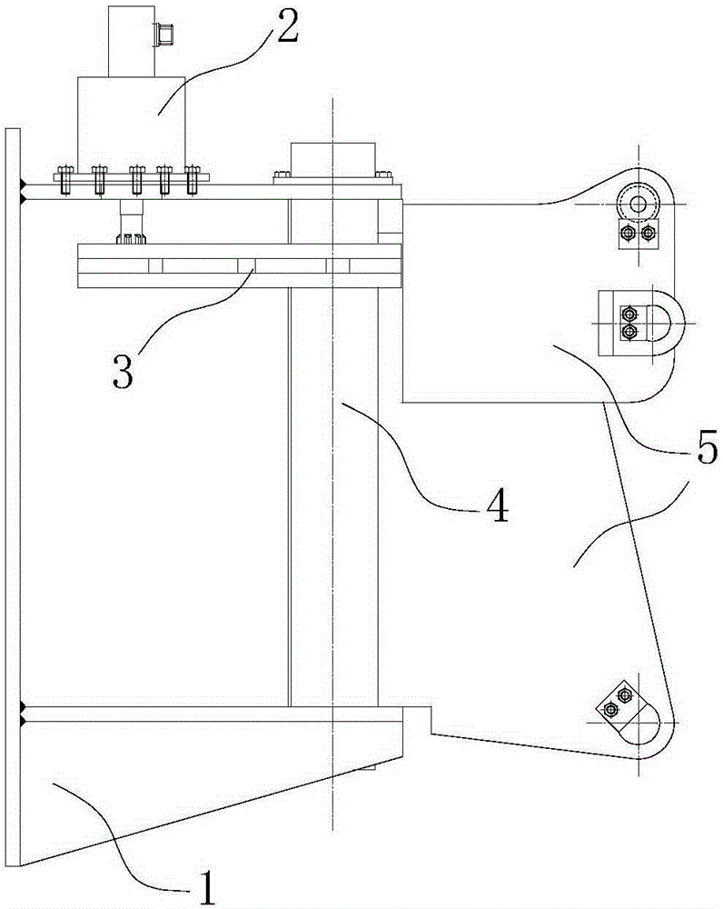
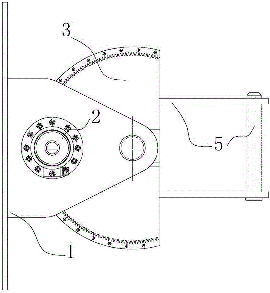
[0024] Such as figure 1 and figure 2 Shown is an embodiment of the rotating mechanism proposed by the present invention. In this embodiment, the rotating mechanism is used to rotatably connect the platform service basket of the ocean drilling platform to the derrick. In other implementation manners, the rotating mechanism can also be used in other devices, which is not limited thereto. Wherein, in this embodiment, the rotating mechanism mainly includes a fixed seat 1 , a rotating shaft 4 , a reduction gear 3 , a main arm connecting structure 5 and a hydraulic motor 2 .

[0025] Such as figure 1 and figure 2 As shown, in this embodiment, the fixing base 1 is fixed on the derrick and the fixing base 1 mainly includes a top plate and a bottom plate. Wherein the top plate is horizontally fixed to the derrick, and the top plate has a far end away from the derrick. The bottom plate is horizontally fixed on the derrick, and the interval is located below the top plate, and the...

Embodiment approach 2

[0028] Another embodiment of the rotating mechanism proposed by the present invention. In this embodiment, the structure of the rotating mechanism is roughly the same as that of the first embodiment, the difference is that the rotating shaft is vertically fixed on the fixed seat, the deceleration chainring is arranged on the rotating shaft and can rotate around the rotating shaft, the platform service basket and the decelerating The chainring is fixedly connected, or is fixedly connected with the reduction chainring through the main arm connection structure. That is, the driving mechanism drives the reduction toothed disc to rotate around the rotating shaft (through the meshing relationship between the output gear of the hydraulic motor and the reduction toothed disc), and then drives the platform service basket to rotate.


PUM


Abstract

The invention provides a rotating mechanism used for connecting a platform service basket to a derrick in a rotatable mode. The rotating mechanism comprises a fixed base, a rotating shaft, a speed reduction fluted disc and a drive mechanism. The fixed base is fixed to the derrick. The rotating shaft is vertically arranged on the fixed base in a rotatable mode. The platform service basket is fixedly connected with the rotating shaft. The speed reduction fluted disc is fixed to the rotating shaft. The corresponding circle center of the speed reduction fluted disc coincides with the central line of the rotating shaft. The drive mechanism is arranged on the fixed base and used for driving the speed reduction fluted disc to rotate so as to drive the rotating shaft to rotate. Compared with an existing oil cylinder steering mechanism, due to the structure that the drive mechanism drives the rotating shaft to rotate, the service basket fixed to the rotating shaft can have a wider rotation angle range. In addition, compared with an existing motor gear box steering mechanism, the rotating mechanism is simpler in structure and low in manufacturing cost.

Description

technical field [0001] The invention relates to the technical field of offshore platforms, in particular to a rotating mechanism for connecting platform service baskets. Background technique [0002] Platform service baskets (casing service baskets) are widely used in derricks, moon pools or equipment maintenance places of offshore platforms. The service coverage angle and organizational complexity of the platform service basket are important criteria for the quality of marine service basket products. The existing rotating mechanism of the service basket is mainly divided into an oil cylinder steering mechanism or a motor gearbox steering mechanism. Wherein, the oil cylinder steering mechanism is limited by the stroke of the oil cylinder and the arrangement of the mechanism, so that the rotation angle of the service basket is limited. Due to the setting of the gear box, the steering mechanism of the motor gearbox has a complex structure and high cost. [0003] Therefore, ...

Claims


Application Information

Patent Timeline
Patent Type & Authority Applications(China)
IPC IPC(8): E21B41/00F16H19/04
Inventor 王旭辉吴春美宫经海丁全智孙福
Owner TAIZHONG TIANJIN BINHAI HEAVY MACHINERY
Why Eureka
Try Eureka