Spring energy storage device for on-load tap-changer

An energy storage device and on-load tapping technology, which is applied to the power device inside the switch, etc., can solve the problems of low reliability of the spring energy storage device, small rotation angle range of the extension spring driving part, etc., and achieve long relative action time, Satisfy the effect of movement or switching time and improving the speed of action

Active Publication Date: 2014-06-18
SHUANGCHENG ELECTROMECHANICAL TECH DEV
View PDF4 Cites 0 Cited by
  • Summary
  • Abstract
  • Description
  • Claims
  • Application Information

AI Technical Summary

Problems solved by technology

[0005] The present invention aims to solve the problem that the existing over-dead point spring energy storage device has a small rotation angle range of the tension spring driving part, resulting in low reliability of the spring energy storage device, and further provides a spring energy storage device for on-load tap changer. able device

Method used


Image

  • Spring energy storage device for on-load tap-changer
  • Spring energy storage device for on-load tap-changer

Examples


specific Embodiment approach 1

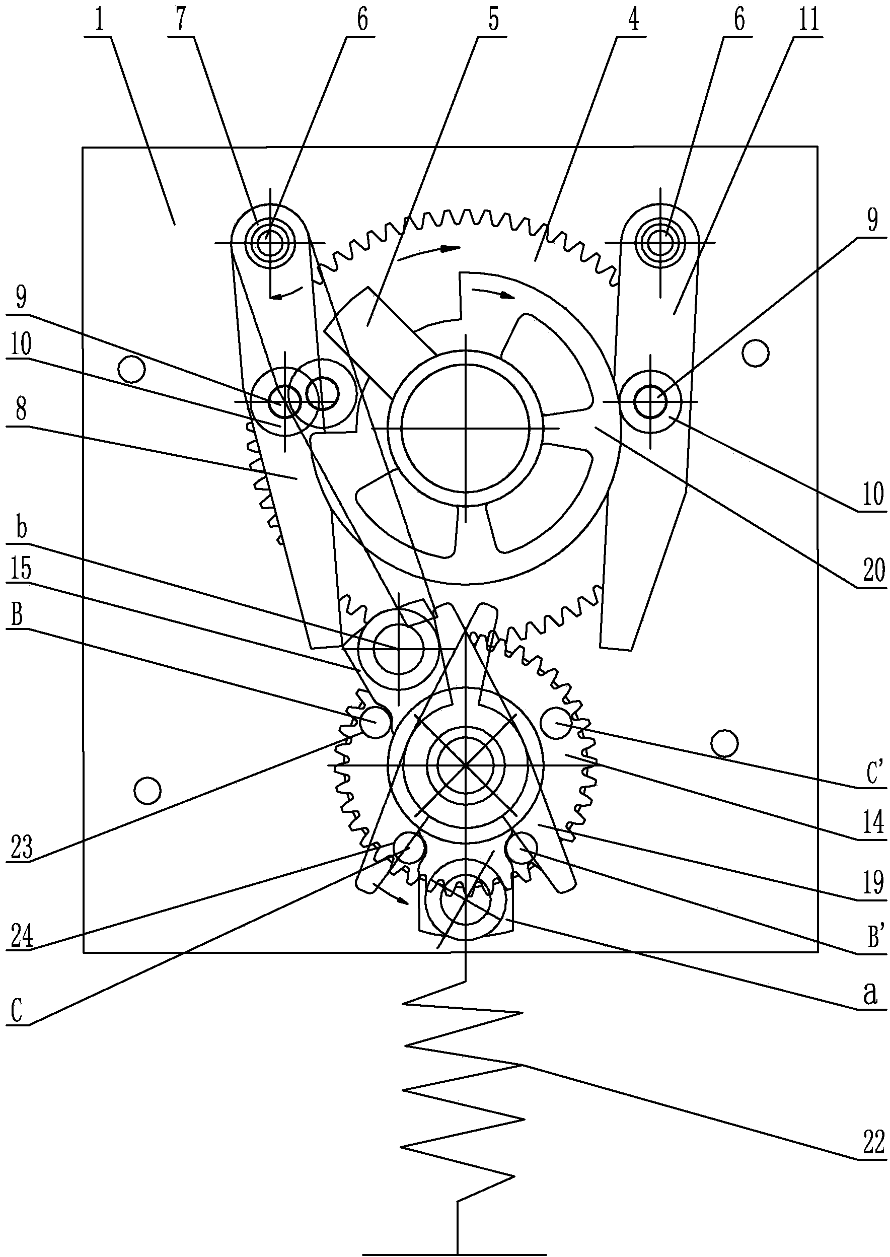
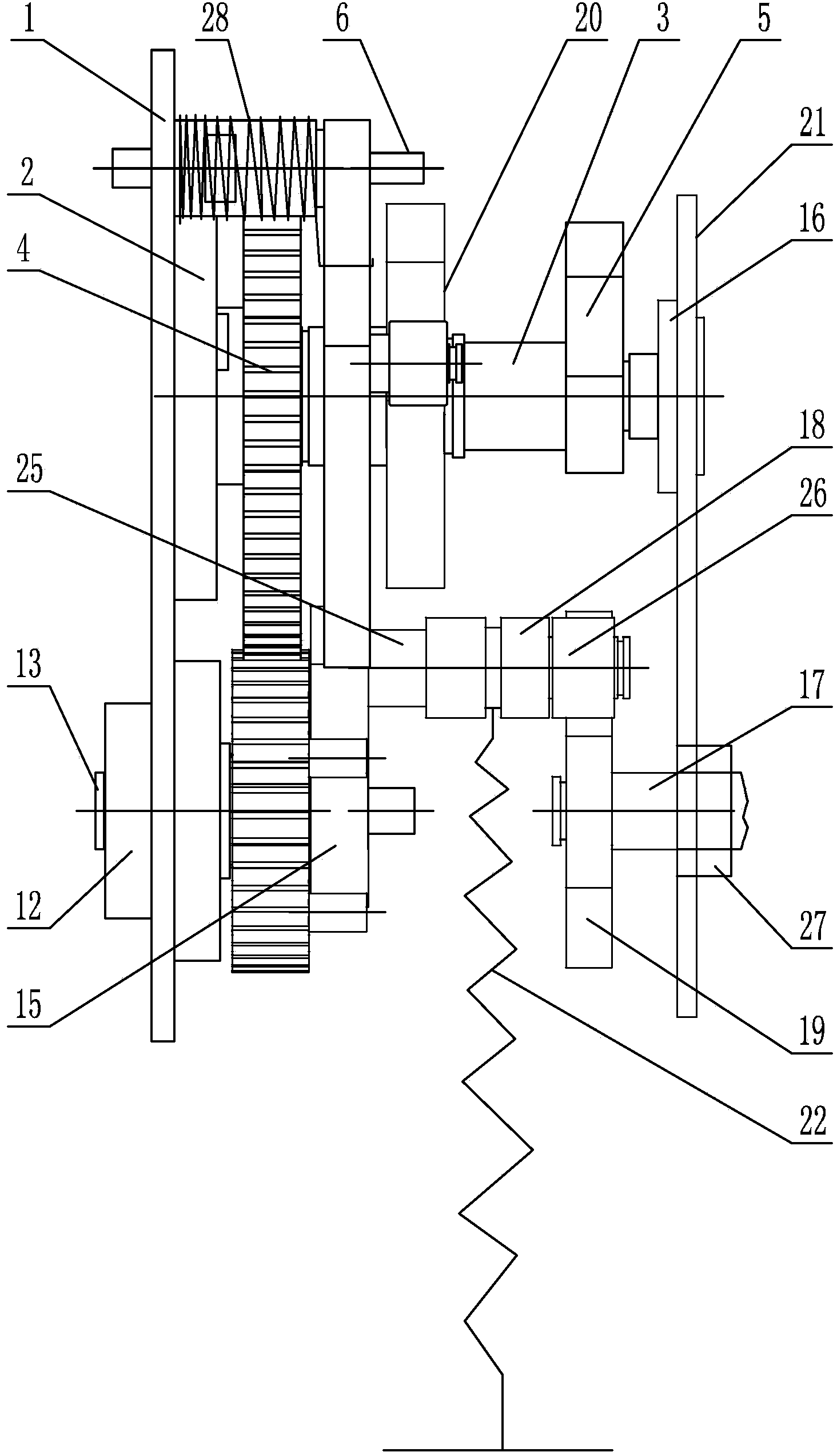
[0017] Specific implementation mode one: as Figure 1-2 As shown, the spring energy storage device of the on-load tap changer in this embodiment includes a side plate 1, a switching bearing seat 2, a switching transmission shaft 3, a switching gear 4, a limit dial block 5, a first limit block 8, a Two limiting blocks 11, the first bearing seat 12, the second transmission shaft 13, the transmission gear 14, the switch shifting block 15, the second bearing seat 16, the third transmission shaft 17, the transmission shaft sleeve 18, the transmission shifting block 19, the limiter Position wheel 20, switch support plate 21, extension spring 22, the first dial column 23, the second dial column 24, transmission column 25, rotating sleeve 26, the third bearing seat 27, two limit block pillars 6, two limit Block support sleeve 7, two spacer shafts 9, two spacer sleeves 10 and two torsion springs 28;

[0018] The side plate 1 is parallel and vertically arranged with the switch support ...

specific Embodiment approach 2

[0027] Specific implementation mode two: as figure 1 As shown, the limit bushing 10 on the first limit block 8 of this embodiment is applied to the limit wheel 20 under the action of the torsion spring 28 located on the left side, and the direction of the force applied to the limit wheel 20 points to the axis of the switching transmission shaft 3 . With such a design, the limit shaft sleeve 10 can achieve the best limit effect. Other components and connections are the same as those in the first embodiment.

specific Embodiment approach 3

[0028] Specific implementation mode three: as figure 1 As shown, the limit bushing 10 on the second limit block 11 of this embodiment is applied to the limit wheel 20 under the action of the torsion spring 28 located on the left side to point to the axis of the switching transmission shaft 3 . With such a design, the limit shaft sleeve 10 can achieve the best limit effect. Other compositions and connections are the same as those in Embodiment 1 or 2.


PUM


Abstract

The invention provides a spring energy storage device for an on-load tap-changer, and relates to a spring energy storage device. The spring energy storage device aims to solve the problems that according to an existing over-dead-point type spring energy storage device, the rotation angle range of tension spring drive components is small, and therefore the reliability of the spring energy storage device is low. A second transmission shaft is installed on the lower portion of a side plate through a first bearing block. The second transmission shaft and a third transmission shaft are coaxially arranged. A transmission gear is installed on the second transmission shaft and located between the side plate and a switching support plate. The end face, facing a transmission shifting block, of the transmission gear is provided with a first shifting column and a second shifting column. The first shifting column and the second shifting column are integrated with the transmission gear. The second transmission shaft is fixedly sleeved with one end of a switching shifting block. A transmission column is horizontally and fixedly installed to the other end of the switching shifting block. The transmission column is sleeved with a transmission shaft sleeve and a rotating sleeve in sequence. One end of a tension spring is installed on the transmission shaft sleeve, and the other end of the tension spring is fixed through a fixing column. Two limiting shaft sleeves are located on the periphery of a limiting wheel. The spring energy storage device is used for the on-load tap-changer.

Description

technical field [0001] The invention relates to a spring energy storage device of an on-load tap changer. Background technique [0002] At present, the fast mechanism of the on-load tap changer is driven by a spring energy storage device, and the most common one is an over-dead point spring energy storage device. The rotation angle range of the extension spring driving part of the over dead point type spring energy storage device is small, and the maximum angle is only 90 degrees. [0003] The action time of the fast mechanism of the on-load tap-changer has strict requirements. The action cannot be too fast. Too fast action time will directly affect the reliability of the product. The tension of the extension spring determines the length of the action time, so the design of the extension spring tension It cannot be too large, that is, the surplus coefficient of the tension spring force is relatively small. When the lubrication of the fast mechanism of the on-load tap-chang...

Claims


Application Information

Patent Timeline
Patent Type & Authority Applications(China)
IPC IPC(8): H01H3/30
Inventor 王继忠
Owner SHUANGCHENG ELECTROMECHANICAL TECH DEV
Why Eureka
Try Eureka