
Assembling method of electromagnetic valve assembly

An assembly method and solenoid valve technology, which are applied in the valve operation/release device, valve device, valve details, etc., can solve the problems of easy over-pressing, the valve seat is not pressed in place, the air gap G becomes larger, etc. The effect of manufacturing yield, increasing reliability, and simplifying assembly structure

Active Publication Date: 2011-08-03
WUHU BETHEL ELECTRONICS CONTROL SYST
View PDF5 Cites 10 Cited by
  • Summary
  • Abstract
  • Description
  • Claims
  • Application Information

AI Technical Summary

Problems solved by technology

Since the valve seat and the valve housing are tightly fitted by interference, and there is no limit surface between the two parts, it is easy to press too much during press-fit assembly, or because of the elastic deformation of the material, after the press-fit is completed and the pressure is removed The valve seat rebounds, causing the valve seat not to be pressed in place, or due to the repeated action of electromagnetic force during the long-term use of the valve, the valve seat will have a relative displacement with the valve housing, making the air gap G larger
Therefore, in order to control the pressing stroke very accurately, the requirements for dynamic displacement monitoring and pressure control of the manufacturing equipment are very high. Even so, the scrap rate in the manufacturing process is also high, and the reliability of the valve cannot be well guaranteed.

Method used


Image

  • Assembling method of electromagnetic valve assembly
  • Assembling method of electromagnetic valve assembly
  • Assembling method of electromagnetic valve assembly

Examples


Embodiment Construction

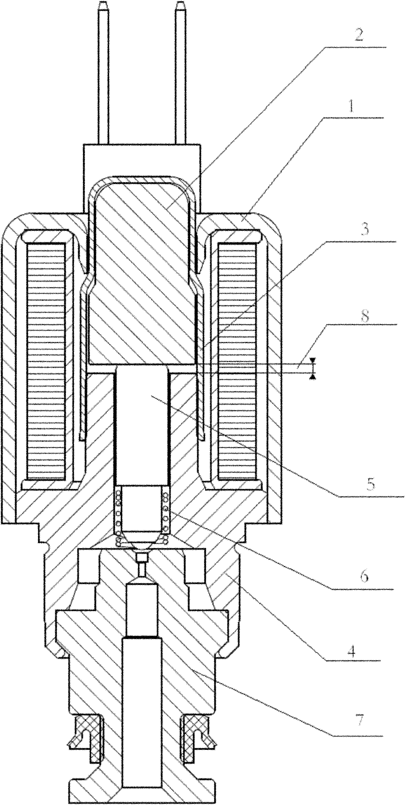
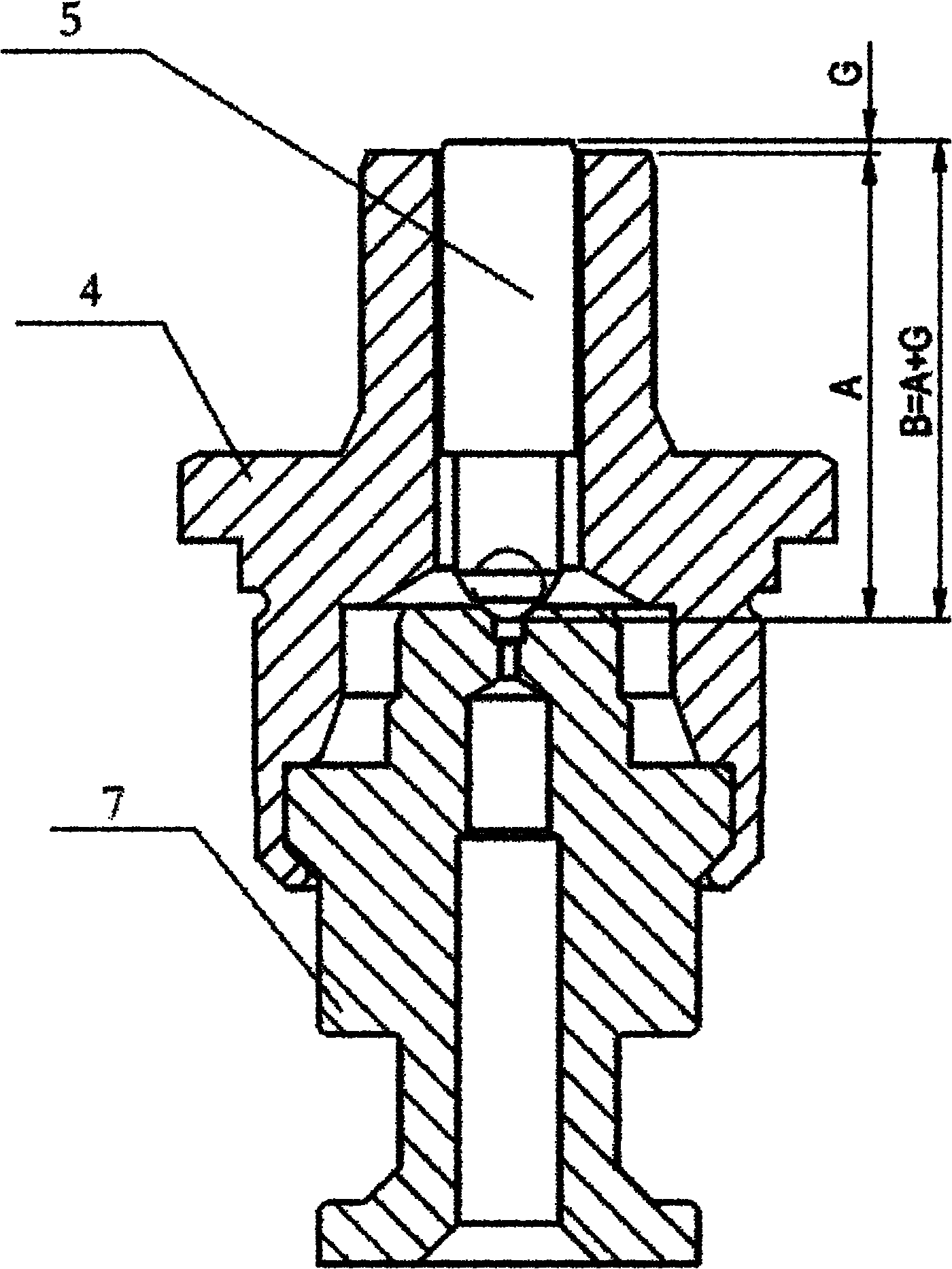
[0021] Such as figure 2 , 3 , 4 shows the schematic diagram of the solenoid valve structure. It can be seen that the valve seat 7 is inserted into the valve casing 4, and the valve casing 4 is in the shape of a hole step at the end where the valve seat 7 is inserted. After the valve seat 7 is inserted, it is stuck in this hole step and riveted with the valve casing 4. . The size of the valve stem 5 of the present invention is determined after the valve seat 7 and the valve housing 4 are installed. As long as the required size of the valve stem 5 is accurate, the accuracy of the air gap 8 can be guaranteed, which reduces unstable factors and improves the reliability of the product. sex.

[0022] The determination of above-mentioned valve stem 5 and its installation scheme are as follows:

[0023] Step a: Determine the possible required length range of the valve stem 5 according to the processing error and the mutual assembly error related to the valve casing 4 and the valve...


PUM


Abstract

The invention discloses an assembly structure of an electromagnetic valve, which comprises a valve sleeve, a valve shell, an armature, valve rods, a restoring spring and a valve seat, wherein one end of the valve shell, which is inserted to the valve seat, is provided with a hole step, the valve seat is inserted to the shell and riveted in the hole step, the valve rods are placed in groups in advance and then taken and installed according to the specific needs of the valve seat and the valve shell, and therefore, by adopting the selection and installation mode of the valve rod, the electromagnetic valve can be assembled rapidly and accurately.

Description

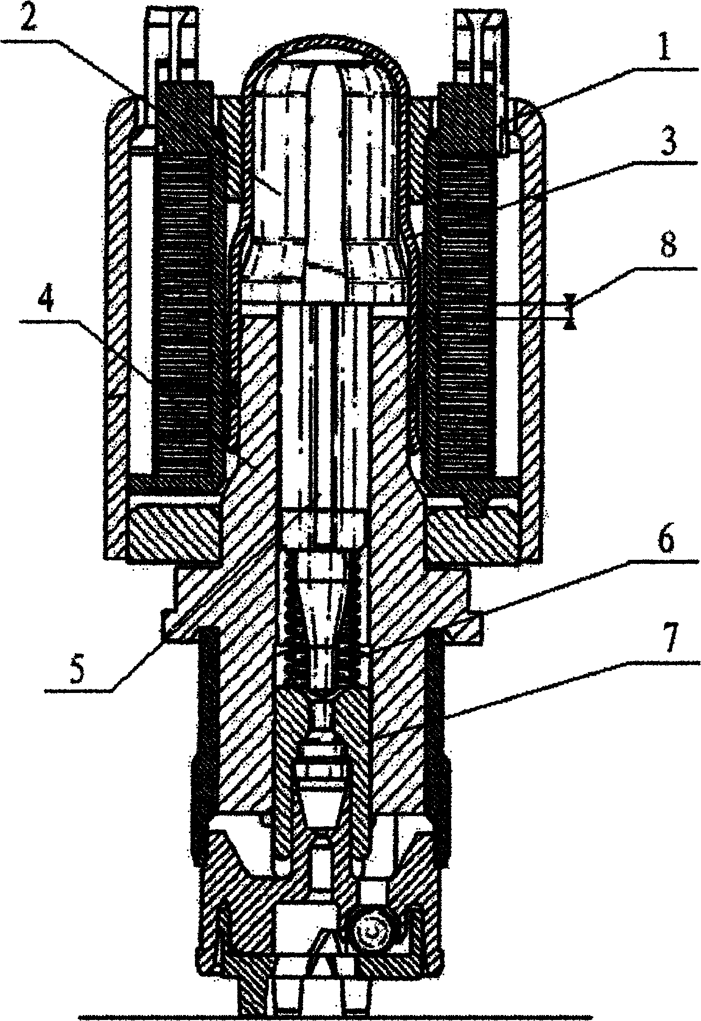
technical field [0001] The present invention relates to a method for assembling a solenoid valve used in a hydraulic control device, in particular to a solenoid valve used in an anti-lock brake system (ABS system) or an electronic stability program system (ESP system) of an automobile. A method of assembling a valve assembly structure for a valve. Background technique [0002] Common solenoid valves, such as figure 1 As shown (with the valve open), there is a purely mechanical valve assembly in addition to the solenoid assembly. The valve assembly includes a valve sleeve, a valve casing, an armature, a valve stem, a return spring, and a valve seat. Seal welding is performed between the valve sleeve and the valve casing, and the valve sleeve and the valve casing withstand the pressure generated in the hydraulic system. , and transmit this pressure downward to a fluid component (not shown), the upper end of the armature sticks to the inner wall of the valve sleeve, and the l...

Claims


Application Information

Patent Timeline
Patent Type & Authority Applications(China)
IPC IPC(8): F16K31/06
Inventor 水浩峻危红星向世水覃赞文
Owner WUHU BETHEL ELECTRONICS CONTROL SYST
Learn More