Double-barrelled automatic slag adding machine

A technology of automatic slag feeding machine and feeding pipe, which is applied in the field of double-pipe automatic slag feeding machine, can solve the problems of high crushing rate of pipes and mold slag, easy wear of elbows and pipes, increase the width of slag feeding machine, etc., and achieve structural Compact, uniform slag addition, high degree of automation

Inactive Publication Date: 2012-12-12
WUHAN UNIV OF SCI & TECH
View PDF2 Cites 0 Cited by
  • Summary
  • Abstract
  • Description
  • Claims
  • Application Information

AI Technical Summary

Problems solved by technology

[0003] In recent years, foreign countries have developed different types of mold powder automatic slag adding machines, the main disadvantages of which are: long conveying pipeline, easy wear of elbows and pipes, mold slag blocking pipelines and high crushing rate of mold slag; The "Slab Continuous Casting Mold Mold Slag Automatic Adding Device" (CN 202549392A) patented technology, this automatic slag adding device is installed on the side of the mold, it is not suitable for the occasion where the installation space is small and multiple molds are arranged side by side ; In addition, the patented technology of "automatic slag adding device for large-section crystallizer" (public number CN202247962A), the slag bucket of this device moves in the width direction of the slag adding machine, which increases the width of the slag adding machine, and the protective slag is in the slag adding pipe The outlet of the slag feeder falls freely and is prone to uneven phenomena. The height direction of this slag feeder cannot be changed, so it is not suitable for crystallizers of different heights

Method used


Image

  • Double-barrelled automatic slag adding machine
  • Double-barrelled automatic slag adding machine
  • Double-barrelled automatic slag adding machine

Examples


Embodiment Construction

[0038] The following further describes the present invention in conjunction with the accompanying drawings and specific embodiments, without limiting the scope of protection:

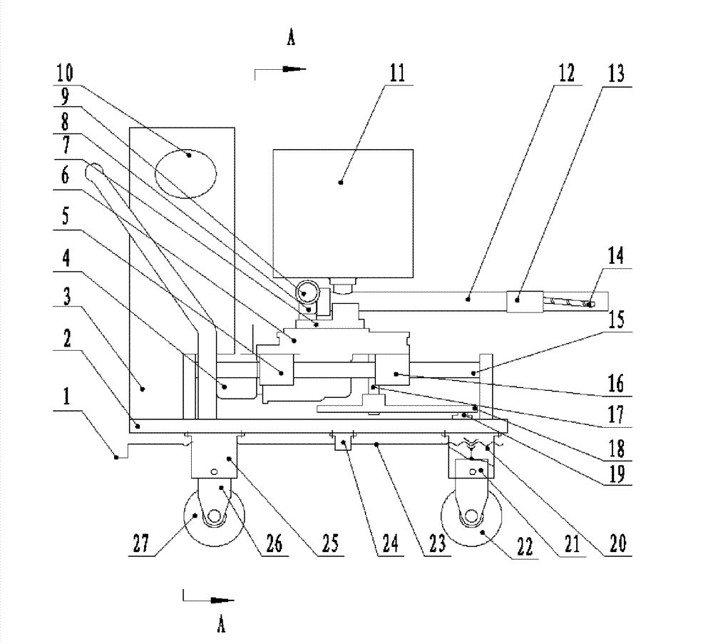
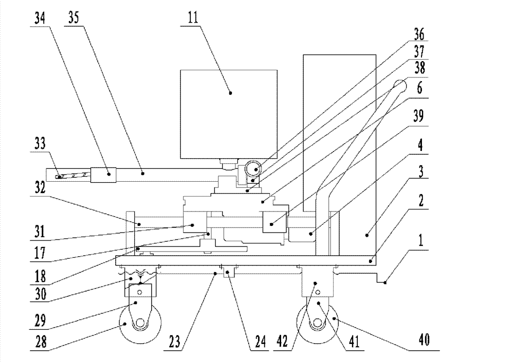
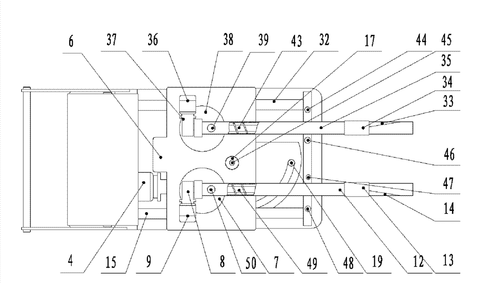
[0039] A double-pipe automatic slag adding machine, such as figure 1 , figure 2 , image 3 with Figure 4 As shown, it is composed of a frame, a slag adding system and an electronic control system; the slag adding system is installed in the front of the frame 2, and the electronic control system is installed in the rear of the frame 2.

[0040] The structure of the slag adding system is: the output shaft of the swing motor 4 is connected to the input shaft of the third reducer 6 through a coupling, and the first feed pipe swing output shaft and the second feed pipe swing output of the third reducer 6 The shafts are respectively keyed to the first conveying pipe support plate 7 and the second conveying pipe support plate 38. The first conveying pipe support plate 7 and the second conveying pipe support plate ...


PUM


Abstract

The invention relates to a double-barrelled automatic slag adding machine. The technical scheme comprises that the slag adding machine comprises a frame, a slag adding system and an electric control system. The slag adding system is in the structure that: a vibrating motor (4) respectively drives two feed delivery pipe supporting discs (7 and 38) to rotate by virtue of two vibrating output shaftsof a third reduction box (6), namely a first feed delivery pipe (12) and a second feed delivery pipe (35) are driven to vibrate in the horizontal plane; and a translation compensation output shaft (17) of the third reduction box (6) drives a translation compensation cam (18) to rotate, thus the reciprocating linear motion of the slag adding system is realized. Two feed delivery motors (9 and 36) respectively drive a first feed delivery screw rod (49) and a second feed delivery screw rod (43) to rotate, thus a granular material is pushed towards the exit direction. The slag adding machine provided by the invention has the characteristics of compact structure, uniform slag addition, high degree of automation and wide application range and is simple in operation and applicable to automatic, continuous and uniform casting powder addition of a large-section crystallizer of which all the material spreading regions have the lengths in the range of 300-2500mm and the widths in the range of 0-300mm.

Description

Technical field [0001] The invention belongs to the technical field of automatic slag adding machines. Specifically relates to a double-pipe automatic slag adding machine. Background technique [0002] Continuous steel casting generally uses mold powder, usually with 4-20% pure fluorine in the mold powder, and the slag consumption is about 2.5kg / t steel. In the production process, because workers are in an environment with a high fluorine concentration, it is not only harmful to health, but also the randomness of artificial slagging is large, and the slag layer is uneven, which easily causes problems such as slag entrapment, which affects the surface and internal quality of the cast slab. Therefore, the automatic adding slag technology of continuous casting mold powder has attracted the attention of technicians. [0003] In recent years, foreign countries have developed different types of mold powder automatic slag adding machines. The main disadvantages are: long conveying pipel...

Claims


Application Information

Patent Timeline
Patent Type & Authority Patents(China)
IPC IPC(8): B22D11/108
Inventor 陈新元谢剑刚陈奎生曾良才傅连东湛从昌张喆郭媛邓江洪杨文军黄富瑄
Owner WUHAN UNIV OF SCI & TECH
Why Eureka
Try Eureka