Eureka AIR delivers breakthrough ideas for toughest innovation challenges, trusted by R&D personnel around the world.

Brush component of vacuum cleaner

A technology for vacuum cleaners and brushes, applied in suction filters and other directions, can solve the problems of inability to effectively collect hair and pet hair, reduce the cleaning efficiency of vacuum cleaners, and reduce cleaning efficiency, achieve compact structure, improve dust collection efficiency, improve The effect of design freedom

Active Publication Date: 2011-08-03
SAMSUNG ELECTRONICS CO LTD
View PDF14 Cites 12 Cited by
  • Summary
  • Abstract
  • Description
  • Claims
  • Application Information

AI Technical Summary

Problems solved by technology

This drastic change of direction of the outside air results in a large pressure loss which reduces the overall cleaning efficiency of the vacuum cleaner
[0006] Furthermore, there is a problem that the cleaning efficiency is lowered because the fine dust floating in front of the brush assembly away from the surface to be cleaned cannot be sucked in.
[0007] And, because only be provided with hairbrush, therefore can't effectively collect the hair on the surface being cleaned and the hair of pet.

Method used


Image

  • Brush component of vacuum cleaner
  • Brush component of vacuum cleaner
  • Brush component of vacuum cleaner

Examples


Embodiment Construction

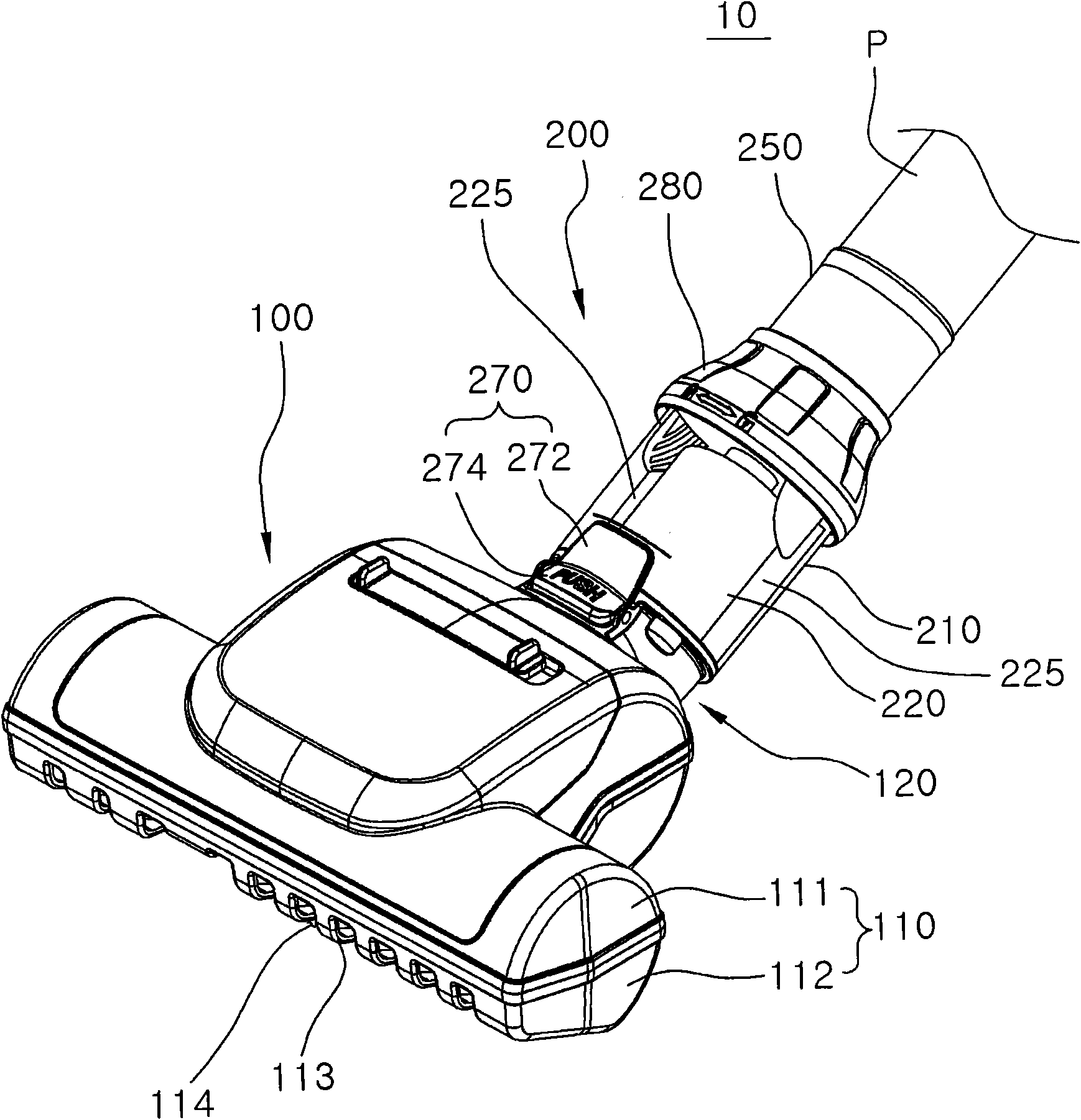
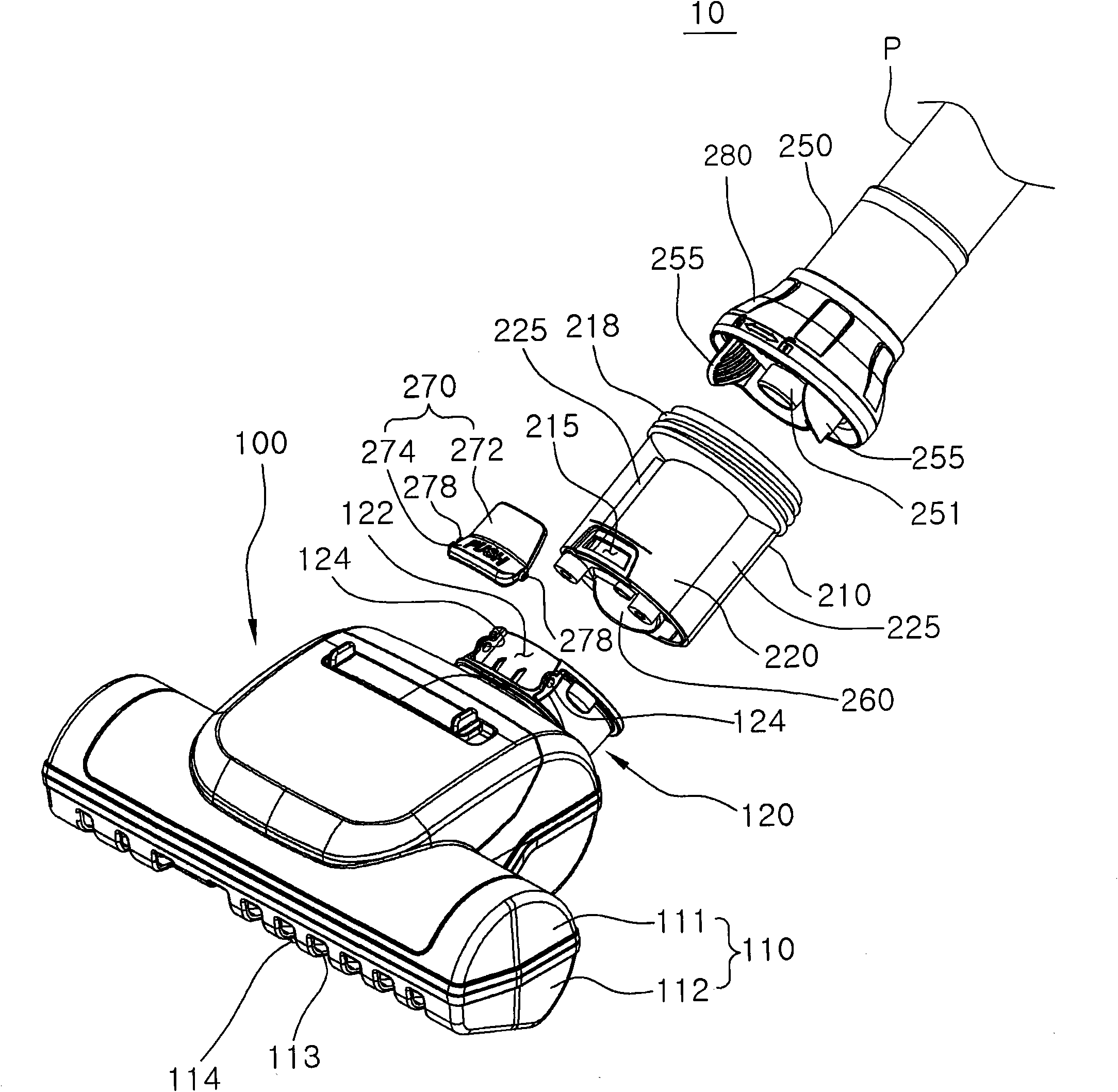
[0053] Below, refer to Figure 1 to Figure 7 A brush assembly 10 according to a first embodiment of the present invention is explained.

[0054] Such as Figure 1 to Figure 4 As shown, the brush assembly 10 according to the first embodiment of the present invention has a brush unit 100 and a cyclone dust collection unit 200 .

[0055] The brush unit 100 is for sucking air from the surface to be cleaned, and has a housing 110 , a neck 120 , a brush 130 , and a turbo fan 140 .

[0056] The housing 110 has an upper housing 111 and a lower housing 112 . These upper and lower casings 111 , 112 are combined with each other to form the inner space of the casing 110 .

[0057] The opened bottom of the lower case 112 is provided with a plurality of ribs 113 and formed with a plurality of bottom suction ports 114 . The dusty air on the surface to be cleaned is sucked into the inner space of the casing 110 through the bottom surface suction port 114 .

[0058] The neck 120 is a memb...


PUM


Abstract

The invention provides a brush component of a vacuum cleaner which has a compact bulk and can improve dust separation efficiency and reduce pressure loss. The brush component of the invention is characterized in that the component includes: a brush unit with a housing contacting a cleaned surface; a cyclone dust collecting unit with one end connected to the brush unit and the other end connected to an extending pipe of the vacuum cleaner. The cyclone dust collecting unit includes: a cyclone flow path which allows the inflow of a part of the air discharged from the brush unit and separates the dust in the air by centrifugation; a bypass flow path which allows the rest air discharged from the brush unit to move directly to the extending pipe. Additionally, the central axis of the cyclone flow path is parallel to the central axis of the extending pipe.

Description

technical field [0001] The invention relates to a brush assembly of a vacuum cleaner provided with a cyclone dust collection unit. Background technique [0002] Generally, the upright vacuum cleaner uses the brush assembly to suck in the dusty air, and separates the dust in the dust collection device installed inside the vacuum cleaner through the extension pipe and hose, and then discharges the purified air to the outside of the vacuum cleaner body installation. [0003] In canister vacuum cleaners, Korean Laid-Open Patent No. 2007-0087357 discloses a structure in which an auxiliary dust collection device is provided between the brush assembly and the extension pipe assembly. The vacuum cleaner with such a structure sucks air through the brush assembly, and after the dust is separated once in the auxiliary dust collection device, the purified air flows into the dust collection device of the vacuum cleaner body through the extension pipe and hose, and is separated again. F...

Claims


Application Information

Patent Timeline
Patent Type & Authority Applications(China)
IPC IPC(8): A47L9/16
Inventor 吴长根金闵河朴正洙周诚泰梁东宪
Owner SAMSUNG ELECTRONICS CO LTD
Why Eureka
Eureka Blog
Learn More