
Modularized CO2 laser discharge box

A laser, modular technology, used in lasers, laser parts, laser parts and other directions, can solve the problems of non-adjustment, poor uniformity of glow discharge, low precision, etc., and achieve the effect of ensuring independence, firm and reliable insulation

Active Publication Date: 2012-11-14
NINGBO SIASUN ROBOT TECH CO LTD
View PDF0 Cites 0 Cited by
  • Summary
  • Abstract
  • Description
  • Claims
  • Application Information

AI Technical Summary

Problems solved by technology

[0005] 1. The structure of the discharge box is complicated, the design of the water circuit of the anode plate is unreasonable, the processing cost is high, the reliability is poor, and the maintainability is poor
[0006] 2. The adjustability of the discharge box is poor, basically it cannot be adjusted after installation, and it is inconvenient to flexibly adjust the center position of the gain area
[0007] 3. The distance between the cathode needle and the anode plate of the discharge box is installed poorly in manufacturability and precision, resulting in poor uniformity of glow discharge, easy to generate arc discharge, and difficult to ensure stable output of high-power laser
[0008] The tube-sheet type is discharged by a copper tube as the cathode. The copper tube is easy to oxidize, has a short working life, and needs to be cleaned regularly.

Method used


Image

  • Modularized CO2 laser discharge box
  • Modularized CO2 laser discharge box
  • Modularized CO2 laser discharge box

Examples


Embodiment Construction

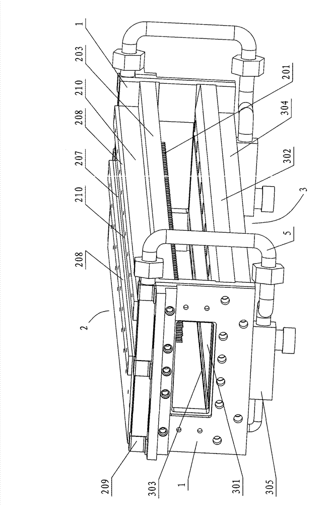
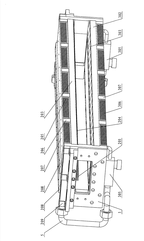
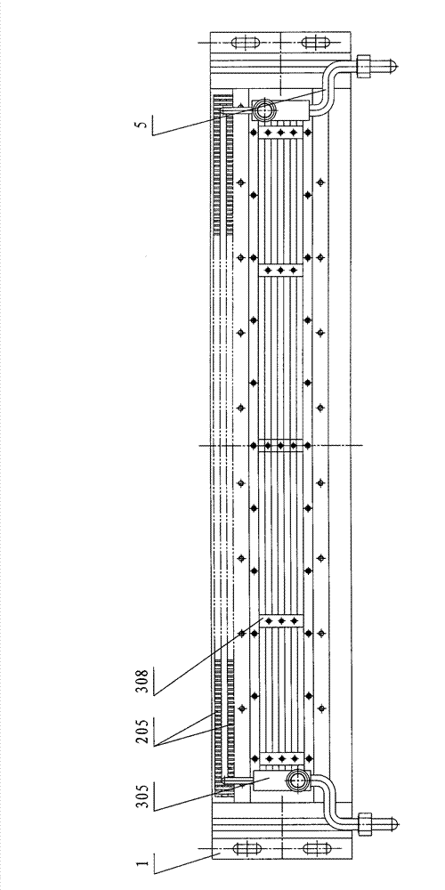
[0036] The present invention will be described in further detail below in conjunction with the accompanying drawings.

[0037] Such as Figure 1~6 As shown, the present invention includes cathode 2 and anode 3, wherein cathode 2 includes cathode discharge needle 201 and cathode support plate 203, anode includes anode plate 301, anode support plate 302 and cooling water pipe 5, cathode support plate 203 and anode support plate 302 The two ends of the cathode are fastened to the end support plates 1 on both sides by screws respectively, and the gas flow channel 4 in the discharge area is formed between the cathode support plate 203 and the anode support plate 302 . The distance between the cathode support plate 203 and the anode support plate 302 can be 45-50 mm, and the distance in this embodiment is 48 mm, which can be adjusted by adjusting the thread height on the end support plate 1 .

[0038] The opposite side of the cathode support plate 203 and the anode support plate 30...


PUM


Abstract

The invention relates to a discharge device of a laser, in particular to a modularized CO2 laser discharge box for generating stable glow discharge by high-voltage direct current excited working gas. The modularized CO2 laser discharge box comprises a cathode and an anode; the cathode comprises cathode discharge needles and a cathode supporting plate; and the anode comprises an anode plate, an anode supporting plate and a cooling water pipe, wherein the cathode discharge needles and the anode plate are arranged on end surface supporting plates on two sides via the cathode supporting plate andthe anode supporting plate respectively; a discharge region airflow passage is formed between the cathode supporting plate and the anode supporting plate; a plurality of cathode discharge needles aredistributed on the cathode supporting plate uniformly; the distance between each cathode discharge needle and the anode plate is equal; and the anode plate is provided with the cooling water pipe fortaking away heat. By the modularized design, the independence, universality and maintainability of various components and parts are guaranteed; a standard gauge block installation manner is adopted for the cathode discharge needles, so the distance between each discharge needle and the anode plate is constant; and the cathode discharge needles are encapsulated on discharge porcelain plates with casting glue, so the modularized CO2 laser discharge box is firm, reliable and good in insulating property.

Description

technical field [0001] The invention relates to a laser discharge device, in particular to a modular CO that generates a stable glow discharge through a high-voltage DC excitation working gas 2 Laser discharge box. Background technique [0002] In industrial lasers, highly stable laser power output is very much pursued; obtaining long-term stable glow discharge is the most basic guarantee for power stability. For this reason, people attach great importance to the design of the discharge system, which is a key core component in laser design. [0003] Currently, cross-flow excitation CO 2 There are mainly three types of laser discharge structures: pin-plate type, tube-plate type, and electron beam sustained discharge. The first two are widely used in industrial production. The needle-plate discharge structure is used to evenly divide the discharge space into several small units, which are individually controlled, so as to realize large-volume stable glow discharge under hig...

Claims


Application Information

Patent Timeline
Patent Type & Authority Patents(China)
IPC IPC(8): H01S3/03H01S3/041H01S3/038
Inventor 官铭辉邢飞陈昭李雨
Owner NINGBO SIASUN ROBOT TECH CO LTD
Learn More