
Steel tube concrete column-double-layer steel plate combined shear wall and construction method thereof

A technology of steel tube concrete columns and combined shear walls, applied in walls, building components, buildings, etc., can solve the problems of poor deformation capacity of concrete walls, affect the seismic performance of high-rise buildings, restrict the flexibility of building layout, etc., and achieve the reduction of formwork The effect of engineering quantity, reduction of foundation cost, improvement of bearing capacity and ductility

Active Publication Date: 2011-07-20
TSINGHUA UNIV
View PDF7 Cites 32 Cited by
  • Summary
  • Abstract
  • Description
  • Claims
  • Application Information

AI Technical Summary

Problems solved by technology

Traditional concrete walls have poor deformation capacity and low ductility, which directly affect the seismic performance of high-rise buildings; excessive vertical loads require a large shear wall thickness to meet the "Seismic Design Code" for shear wall axis The pressure ratio limit; too thick walls increase the weight of the structure, which is not conducive to earthquake resistance, and at the same time increase the cost of the foundation; too thick walls reduce the building area, especially for the commercial ground floor, restricting the flexibility of building layout. Affect the use of functions

Method used


Image

  • Steel tube concrete column-double-layer steel plate combined shear wall and construction method thereof
  • Steel tube concrete column-double-layer steel plate combined shear wall and construction method thereof
  • Steel tube concrete column-double-layer steel plate combined shear wall and construction method thereof

Examples


Embodiment Construction

[0022] The specific implementation method of the present invention will be further described below in conjunction with the accompanying drawings.

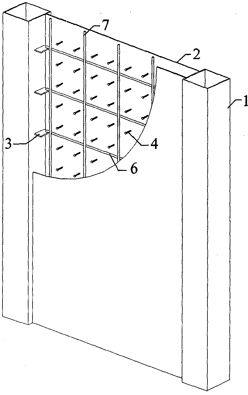
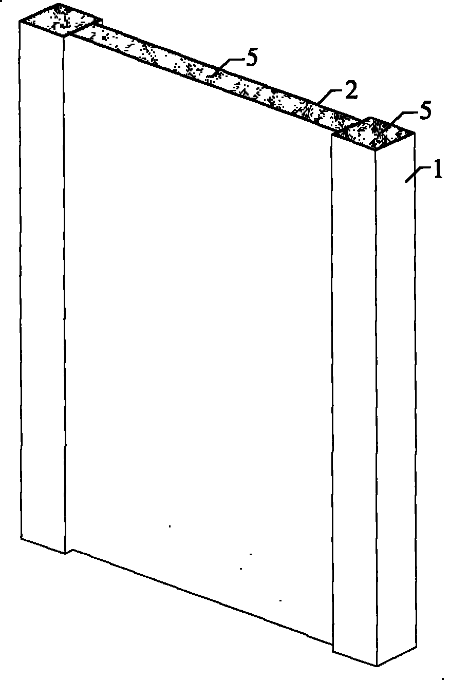
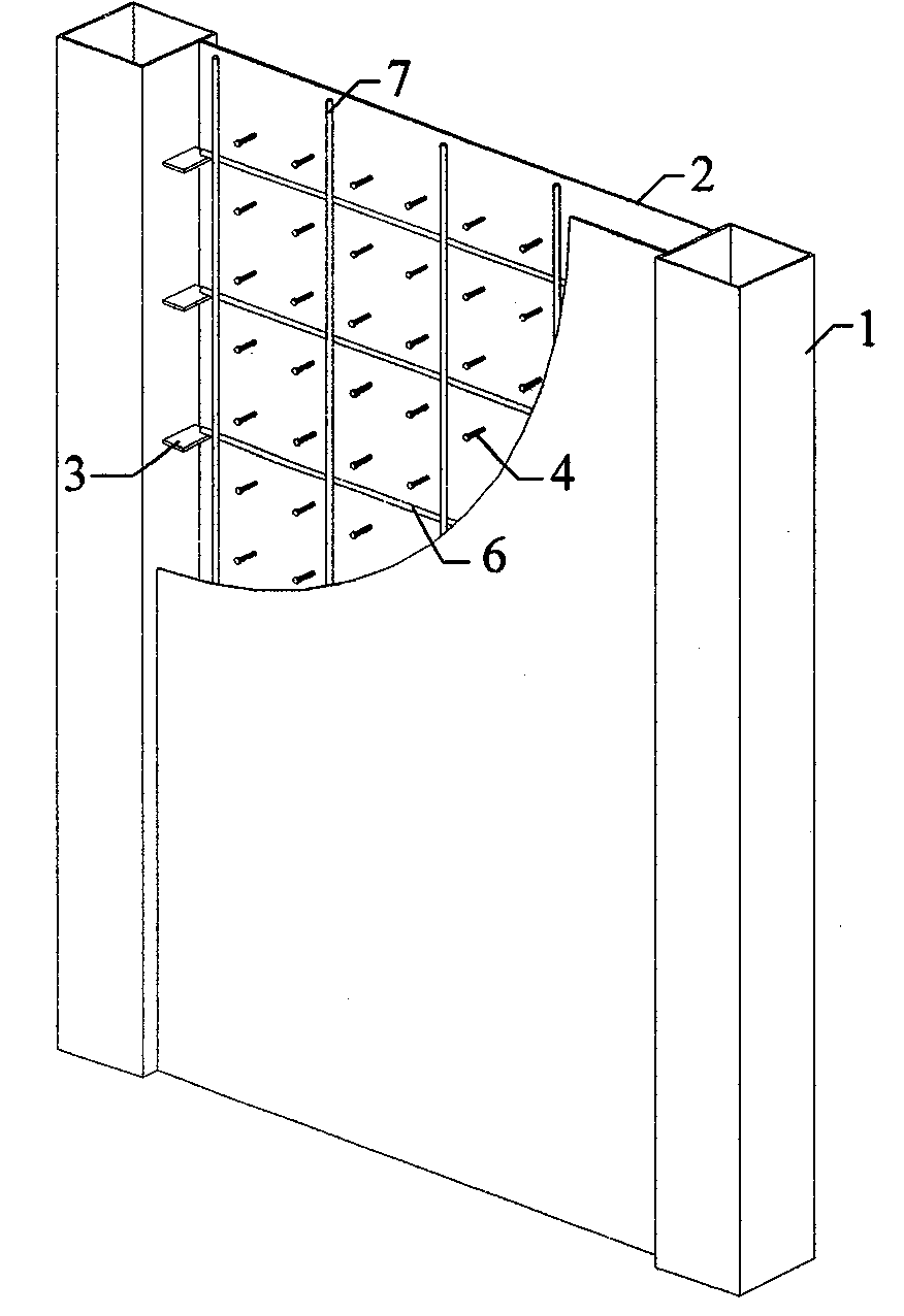
[0023] like Figure 1 ~ Figure 2 As shown, the shear wall includes two steel pipes 1, two steel plates 2, distributed steel bars, connection keys 3, studs 4 and concrete 5; the opposite sides of the two steel pipes are arranged with connection keys 3 vertically , the two ends of the horizontally distributed reinforcing bars in the distributed reinforcing bars are respectively connected to the corresponding connecting keys 3 on the two steel pipes; the two steel plates 2 are welded with studs 4 on the opposite surfaces; the described Both ends of the two steel plates 2 are connected to the steel pipe 1; concrete 5 is poured in the two steel pipes 1 and in the plane enclosed space surrounded by the two steel plates 2 and the two steel pipes 1.

[0024] The steel pipe 1 is circular, square or rectangular. The connections between the...


PUM


Abstract

The invention relates to a steel tube concrete column-double-layer steel plate combined shear wall belonging to the technical field of constructional engineering and combination structures. The steel tube concrete column-double-layer steel plate combined shear wall comprises two steel tubes, two steel plates, distributed reinforcing steel bars, connecting keys, male pins and concrete, wherein the connecting keys are vertically and alternately arranged at the opposite sides of the two steel tubes; both ends of each of transversally distributed reinforcing steel bars in the distributed reinforcing steel bars are respectively connected with the connecting keys in corresponding positions on the two steel tubes; the male pins are welded on the opposite sides of the two steel plates; two lateral ends of the two steel plates are connected with the steel tubes; and concrete is cast in the two steel tubes and in a planar closed space encircled by the two steel plates and the two steel tubes. The shear wall of the invention can restrict the concrete from deforming, improve the bearing capacity and the tensility of the shear wall and enhance the whole quake-proof performance of the structure. Moreover, the shear wall has favorable stress performance and improved quake-proof performance, is favorable to engineering of building space arrangement, decreasing self weight and reducing template engineering and is suitable for being used as a shear wall in a high-rise or ultra-high-rise building.

Description

technical field [0001] The invention relates to a steel pipe concrete column-double-layer steel plate composite shear wall applicable to high-rise and super high-rise buildings, belonging to the technical field of construction engineering and composite structures. Background technique [0002] Shear walls, or cylinders composed of shear walls, are the main lateral force-resisting components of high-rise buildings. With the increase of building height and the improvement of building function requirements, the requirements for all aspects of shear walls are getting higher and higher. Traditional concrete walls have poor deformation capacity and low ductility, which directly affect the seismic performance of high-rise buildings; excessive vertical loads require a large shear wall thickness to meet the "Seismic Design Code" for shear wall axis The pressure ratio limit; too thick walls increase the weight of the structure, which is not conducive to earthquake resistance, and at ...

Claims


Application Information

Patent Timeline
IPC IPC(8): E04B2/86
Inventor 聂建国卜凡民
Owner TSINGHUA UNIV
Learn More