Permanent magnet motor rotor
A permanent magnet motor and rotor technology, which is applied to the rotating parts of the magnetic circuit, the shape/style/structure of the magnetic circuit, etc., can solve the problems of poor mechanical strength and large torque ripple, so as to improve the mechanical strength and reduce the torque ripple. Small, the effect of improving overload capacity and power density
Inactive Publication Date: 2011-06-15
HENAN POLYTECHNIC UNIV
View PDF4 Cites 17 Cited by
- Summary
- Abstract
- Description
- Claims
- Application Information
AI Technical Summary
Problems solved by technology
The built-in permanent magnet synchronous motor superimposes the reluctance torque on the basis of the permanent magnet torque. The existence of the reluctance torque is beneficial to improve the overload capacity and power density of the motor, and it is easy to adjust the speed by weakening the field, but the torque ripple is large. , the magnetic flux leakage is protruding, and the magnetic isolation bridge needs to be designed, and the mechanical strength is slightly poor
Method used
View moreImage
Smart ImageViewing Examples
Examples
Embodiment Construction
Login to View More PUM
 Abstract
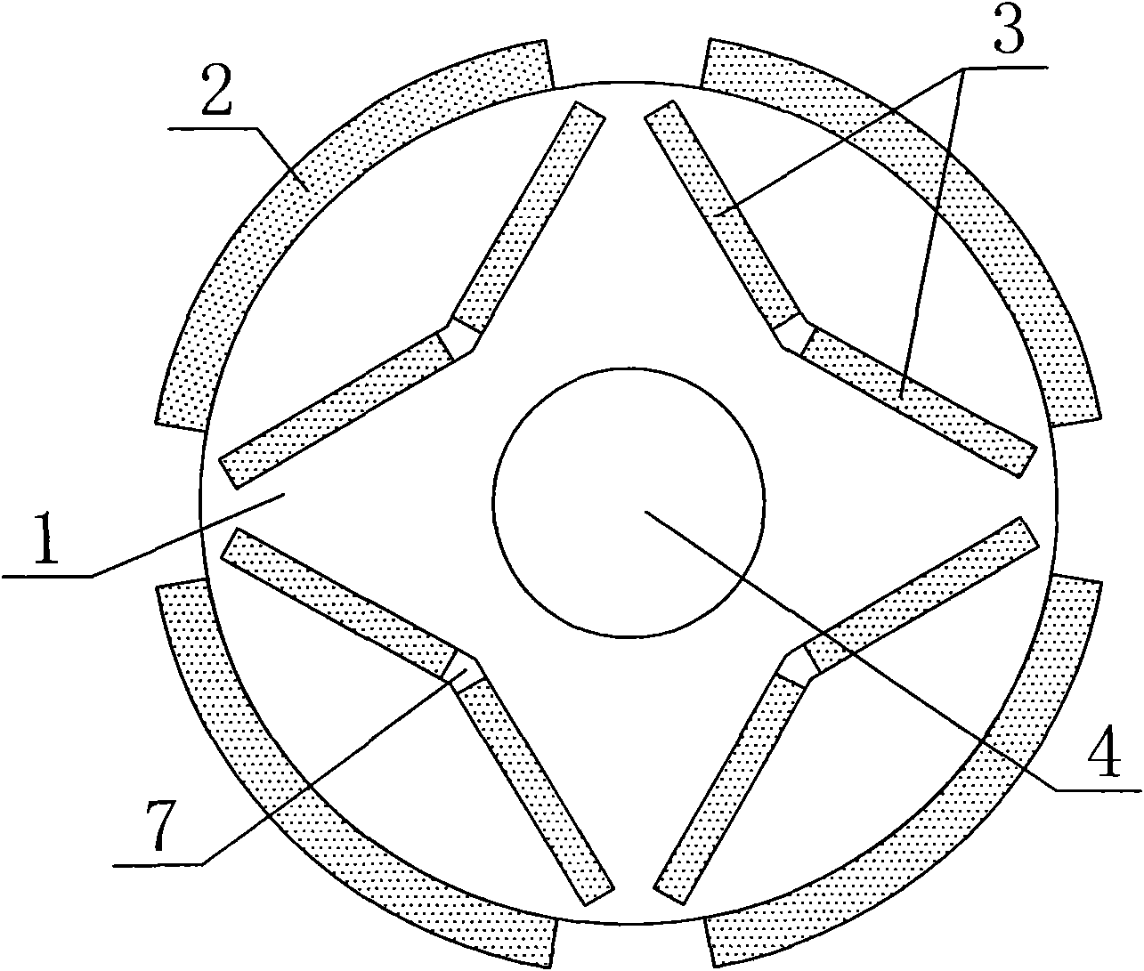
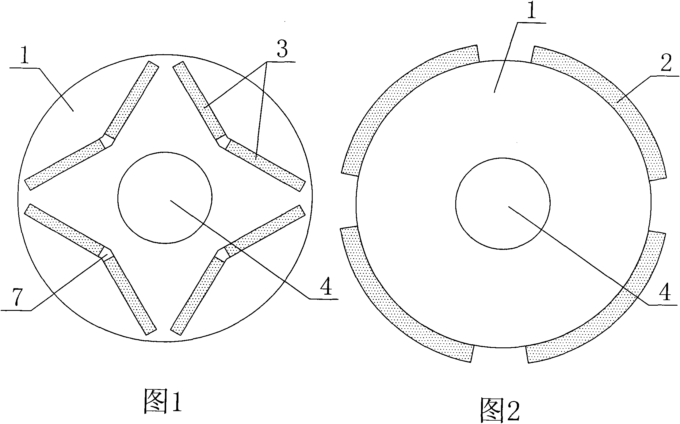
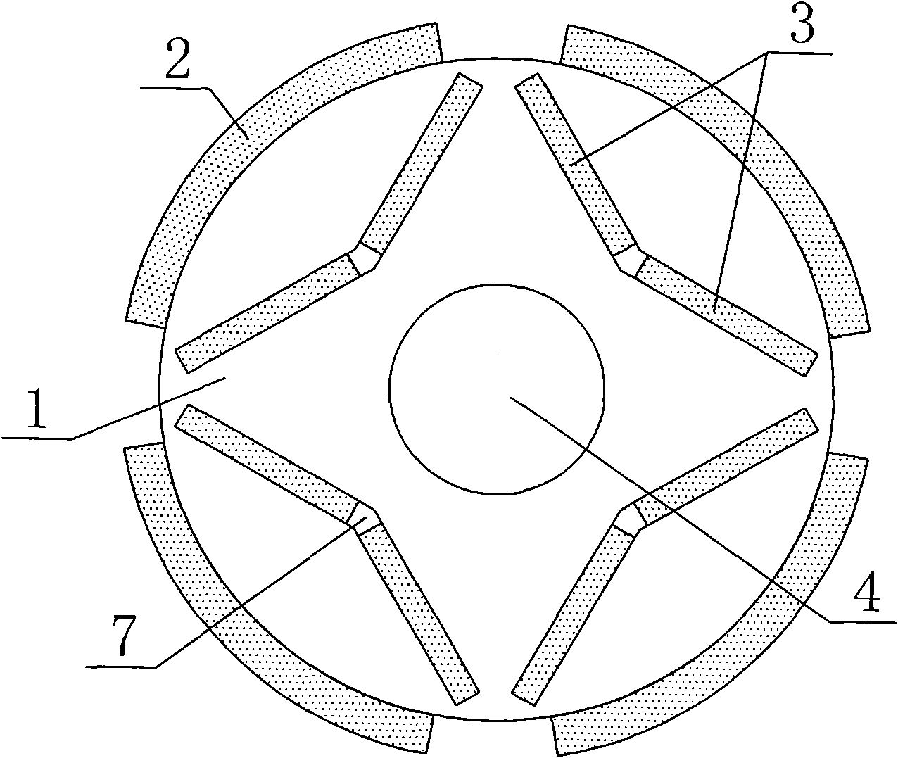
The invention discloses a surface-mounted and interior mixed permanent magnet motor rotor. The rotor comprises a rotor core, tiled permanent magnets, interior permanent magnets and a rotating shaft. The rotor is characterized in that the tiled permanent magnets adhere to the surface of the rotor core, with N and S poles alternate; the interior permanent magnets are inserted into V-shaped slots in the rotor core; the polarity of the two permanent magnets in each V-shaped slot is opposite; and the two permanent magnets form series structure on a magnetic circuit with the corresponding tiled permanent magnet. The rotor has the beneficial effects of enhancing the mechanical strength of the permanent magnet motor, reducing the magnetic flux leakage, omitting the magnetism isolating bridge and improving the starting, braking and operating performances of the permanent magnet motor.
Description
A permanent magnet motor rotor technical field The invention belongs to the technical field of permanent magnet motors, in particular to a permanent magnet motor rotor. Background technique Permanent magnet motors are mainly divided into surface-mounted and built-in structures. The permanent magnets of surface-mounted permanent magnet motors are usually tile-shaped and located on the outer surface of the rotor core. It is characterized by equal direct and quadrature axis inductance. The permanent magnet of the built-in permanent magnet synchronous motor is inserted inside the rotor. There is a pole shoe made of ferromagnetic material between the outer surface of the permanent magnet and the inner circle of the stator core to protect the permanent magnet. The important characteristics of this type of permanent magnet motor The direct and quadrature axis inductances are not equal. Compared with the built-in permanent magnet synchronous motor, the surface-mounted permanent ...
Claims
Login to View More Application Information
Patent Timeline
 IPC IPC(8): H02K1/27
Inventor 司纪凯张丽梅张展封海潮许丹高彩霞许孝卓
Owner HENAN POLYTECHNIC UNIV
- R&D Engineer
- R&D Manager
- IP Professional
- Industry Leading Data Capabilities
- Powerful AI technology
- Patent DNA Extraction
Learn More Browse by: Latest US Patents, China's latest patents, Technical Efficacy Thesaurus, Application Domain, Technology Topic, Popular Technical Reports.
© 2024 PatSnap. All rights reserved.Legal|Privacy policy|Modern Slavery Act Transparency Statement|Sitemap|About US| Contact US: help@patsnap.com


