CT guided lung puncture positioning instrument
A locator and puncture needle technology, which is applied in the field of medical devices, can solve problems such as the limitation of puncture direction, and achieve the effect of improving the success rate and safety
Inactive Publication Date: 2011-06-15
SHANGHAI JIAO TONG UNIV
View PDF7 Cites 17 Cited by
- Summary
- Abstract
- Description
- Claims
- Application Information
AI Technical Summary
Problems solved by technology
After searching the prior art, it is found that the Chinese Patent Document No. CN200977172Y, published on 2007-11-21, records a CT-guided puncture positioning frame, which includes a frame, a U-shaped fixed arm, a directional rod and a fixed plate, and the puncture positioning The operation can only be carried out in a two-dimensional plane, and the puncture direction is greatly restricted
A further search found that the Chinese Patent Document No. CN200977171Y, published on 2007-11-21, recorded a CT positioning puncture angle locator. This technology includes concentric discs, scale lines, and puncture needles. Performed in a two-dimensional plane, the puncture direction is greatly restricted
Method used
View moreImage
Smart ImageViewing Examples


Examples
Embodiment
Login to View More PUM
 Abstract
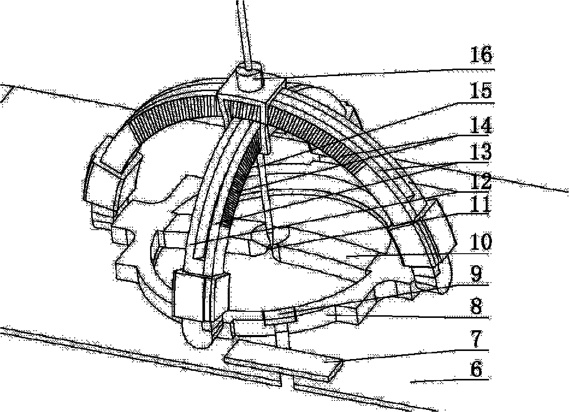
The invention discloses a computed tomography (CT) guided lung puncture positioning instrument in the technical field of medicinal instruments, which comprises a fixing mechanism, a chassis mechanism, two motion arm mechanisms and a puncture guide mechanism, wherein the chassis mechanism is fixedly arranged on the fixing mechanism; the two motion arm mechanisms are rotationally connected with thechassis mechanism from top to bottom respectively, and the first motion arm mechanism is mutually vertical to the second motion arm mechanism; and the puncture guide mechanism sequentially passes through the two motion arm mechanisms and the fixing mechanism and is opposite to the circle center of the fixing mechanism. The positioning instrument has small size, simple structure, accurate positioning, three-dimensional spatial free positioning, simple operating method and the like, can be positioned in a three-dimensional space so as to expand the selection of a puncture channel, avoids the influence of operation on the surgery in a two-dimensional space, avoids deviation of the puncture direction due to human hand fluctuation, and can be quickly detached and withdrawn so as not to affect the subsequent complex operation.
Description
CT-guided lung puncture locator technical field The invention relates to a device in the technical field of medical devices, in particular to a CT-guided lung puncture locator. Background technique Lung biopsy is a commonly used method for diagnosing lung lesions. Before surgery, it is necessary to use medical imaging to diagnose the location and size of the lesion, and plan the puncture target, puncture needle insertion point and puncture depth. Then, after local disinfection of the skin at the needle entry point, lung biopsy surgery under the guidance of medical imaging is performed. Medical imaging is applied to lung biopsy to improve the success rate of puncture and reduce pneumothorax, bleeding and other complications. When the puncture needle reaches the predetermined diseased tissue, the living tissue is collected, the puncture needle is pulled out, and the living tissue is taken out for biopsy. With the rapid development of CT imaging equipment, CT-guided lung bi...
Claims
Login to View More Application Information
Patent Timeline
 IPC IPC(8): A61B19/00A61B17/34
Inventor 夏海豹谢叻
Owner SHANGHAI JIAO TONG UNIV
Features
- R&D
- Intellectual Property
- Life Sciences
- Materials
- Tech Scout
- Unparalleled Data Quality
- Higher Quality Content
- 60% Fewer Hallucinations
Learn More Browse by: Latest US Patents, China's latest patents, Technical Efficacy Thesaurus, Application Domain, Technology Topic, Popular Technical Reports.
© 2025 PatSnap. All rights reserved.Legal|Privacy policy|Modern Slavery Act Transparency Statement|Sitemap|About US| Contact US: help@patsnap.com