Charged test method for current transformer and application thereof
A current transformer and live test technology, which is applied in the direction of instruments, measuring devices, and measuring electrical variables, can solve the problems of long detection cycle, affecting power production, billing, etc.
- Summary
- Abstract
- Description
- Claims
- Application Information
AI Technical Summary
Problems solved by technology
Method used
Image
Examples
Embodiment 1
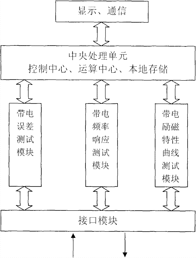
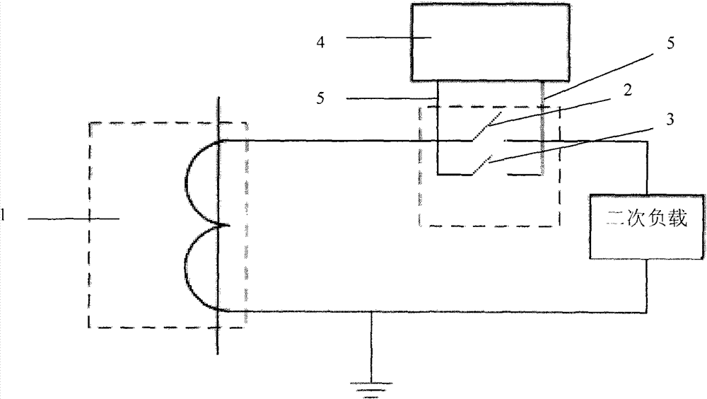
[0030] like figure 2 As shown, an analyzer includes the functions of live error test, live frequency response test and live excitation characteristic curve test. like figure 1 As shown, during the on-site live test, the analyzer 4 with the above functions is used to be connected in series with the secondary circuit of the single-phase current transformer 1 under test, and the live test of the current transformer 1 under test is carried out. The steps of the live test method are as follows:
[0031] First, keep the switch A2 and switch B3 of the secondary terminal box on the secondary side circuit of the current transformer under test 1 closed, and keep the current transformer under test 1 running with power on.
[0032] The second step is to turn on the switch A 2 of the secondary terminal box of the current transformer 1 under test, and then connect the two test line terminals 5 of the analyzer 4 to both sides of the switch of the secondary terminal box.
[0033] The third...
Embodiment 2
[0045] like figure 1 , figure 2 As shown, the same place as in Embodiment 1 will not be repeated, and the difference is that the analyzer 4 is connected in series with the secondary circuit of the three-phase current transformer 1 under test, and the live test of the current transformer 1 under test is carried out. .
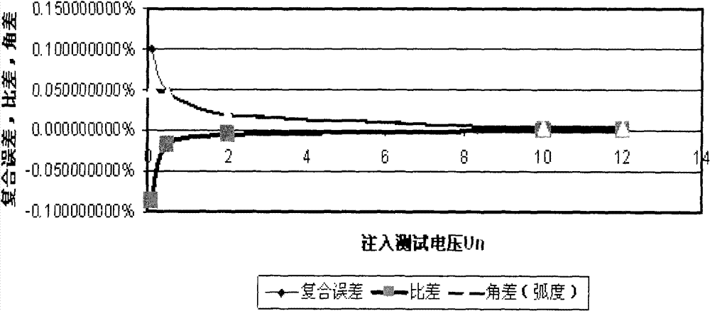
[0046] The fifth step is to select the live frequency response test: the analyzer 4 injects a different-frequency test voltage sequence different from the power frequency into the secondary circuit, and the test voltage sequence is a sine wave of a non-power frequency frequency, and the loop admittance of the corresponding frequency is tested. That is, the value of the response current divided by the injected test voltage Y = I U = g - jb , Where g is the conductance, b is the susceptance, and j is the imaginary unit. Suppose the injection test ...
Embodiment 3
[0050] like figure 1 , figure 2 Shown, the place identical with embodiment 1 no longer repeats narration, and difference is:
[0051] The fifth step is to select the live excitation characteristic curve test: the analyzer 4 first tests the secondary circuit current I of the current transformer 1 under test 0 ; Then according to the secondary rated current I input in the third step s =5A, secondary rated load Z s = 2 ohms, the accurate limit value coefficient is 10, calculate the secondary rated voltage U of the measured current transformer 1 s =I s × Z s =10V, the secondary maximum voltage is 10×U s =100V, the secondary maximum impedance is 100V / 5A=20 ohms; then the resistance sequence generated by the internal resistance sequence of analyzer 4 between 0-20 ohms is connected to the secondary circuit, and the voltage sequence under the resistance condition is tested respectively u n and current sequence I n , according to the current sequence of the test I n and the ...
PUM
 Abstract
Description
Claims
Application Information
 - Generate Ideas
- Intellectual Property
- Life Sciences
- Materials
- Tech Scout
- Unparalleled Data Quality
- Higher Quality Content
- 60% Fewer Hallucinations
Browse by: Latest US Patents, China's latest patents, Technical Efficacy Thesaurus, Application Domain, Technology Topic, Popular Technical Reports.
© 2025 PatSnap. All rights reserved.Legal|Privacy policy|Modern Slavery Act Transparency Statement|Sitemap|About US| Contact US: help@patsnap.com


